Using the SC140 Enhanced OnCE™ Stopwatch Timer Application Note by Kim-Chyan Gan and Yuval Ronen AN2090/D Rev.
OnCE is a trademark of Motorola, Inc. This document contains information on a new product. Specifications and information herein are subject to change without notice. Motorola reserves the right to make changes without further notice to any products herein.
Abstract and Contents In software application development on embedded devices, optimization is critical. Optimized code provides not only faster processing speed but also lower power consumption and longer battery life. Optimized code also minimizes CPU load, enabling more applications to fit into a single chip. In selecting a processor for a system, it is important to understand and compare the speed of execution of different processors.
7 Conclusion . . . . . . . . . . . . . . . . . . . . . . . . . . . . . . . . . . . . . . . . . . . . . . . . . . . . . . . . . . 17 8 References . . . . . . . . . . . . . . . . . . . . . . . . . . . . . . . . . . . . . . . . . . . . . . . . . . . . . . . . . .
1 Introduction A stopwatch timer is an apparatus for measuring the exact duration of an event. Measuring time during execution of code on a Digital Signal Processor (DSP) is useful to identify opportunities for code optimization, to understand system loading, and to compare execution speeds of different processors. This application note presents techniques to implement a stopwatch timer on the StarCore, SC140, using the built-in features of the DSP’s Enhanced On-Chip Emulation (OnCE) module.
2 SC140 Enhanced OnCE Stopwatch Timer Capabilities This section presents the features of the Enhanced OnCE stopwatch timer and the resources required for implementation. The capabilities of the implementation of the stopwatch timer are also explained. 2.1 Features The Enhanced OnCE stopwatch timer provides the following features: • A 64-bit counter, incrementing on each DSP clock cycle. The counter is less susceptible to overflow with 64-bit precision.
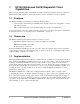
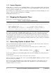
3 Setting Up the Stopwatch Timer Within an Application This section describes the operations necessary to initialize, start, and stop the stopwatch timer within an application. The sequence of operations is shown in Figure 1. Additionally, this section presents the conversion of cycles to actual time and puts all the application code together. Finally, this section explains how to adapt the stopwatch timer code to other SC140-based devices.
Initializing the stopwatch timer consists of setting up the Address Event Detection Channel (EDCA). The role of EDCA in the stopwatch timer implementation is to trigger the commencement of the cycle countdown. The Enhanced OnCE supports six EDCAs. The implementation presented in this application note uses EDCA1, though this choice is arbitrary. Set up of the EDCA requires initializing the following four registers: • The 32-bit EDCA reference value register A (EDCA1_REFA).
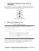
32-bits of the flag variable’s address are used. Thus, EDCA1_MASK is set to 0xffffffff, meaning all address bits will be compared. 3.2 Starting the Stopwatch Timer The C code to start the stopwatch timer is shown in Code 2. Code 2. C Code to Start the Stopwatch Timer #include “EOnCE_registers.
3.2.2 Counter Registers ECNT_VAL is a countdown counter, and ECNT_EXT is a countup counter. ECNT_VAL is decremented on each occurrence of an event, as specified in the control register. ECNT_EXT is incremented each time there is an underflow in ECNT_VAL. For maximum cycle counting capacity, the stopwatch timer implementation initializes ECNT_VAL to the largest possible value which is 4294967295, or 0xffffffff. ECNT_EXT is initialized to zero. 3.
Code 4.
3.6 Adapting Stopwatch Timer Code to Other SC140 Devices The stopwatch timer implementation controls the Enhanced OnCE by writing to its memory-mapped registers. The addresses of these registers are determined in the memory map of the device in which the SC140 core is embedded. The offset between the base address of the memory-mapped peripherals and the addresses of the Enhanced OnCE registers is the same across SC140-based devices.
Figure 4. Finding the Starting Address in the Debugger After finding the starting address, the event detector can be setup. The procedures are outlined in these steps: 1. Choose EOnCE > EOnCE Configurator > EDCA1. 2. Click PC in the “Bus Selection” box. 3. Enter the address of the first instruction in the measured code into the “Comparator A Hex 32-bits” box. 4. Click Enable in the “Enabled after Event On” box. Figure 5 on page -10 shows the event detection settings after performing these steps.
Figure 5. Event Detection Settings 4.1.2 Setting Up the Event Counter The event counter is configured to the same mode as described in Section 3.2.1, “Event Counter Control,” on page -5, except this time the configuration is made using the debugger windows: 1. Choose EOnCE > EOnCE Configurator > Counter. 2. Click Core Clock in the “What to count” box. 3. Click EDCA1 in the “Enable after Even On” box. 4. Type “0xffffffff” in the “Event Counter Value (Hex 32 bits)” box. 5.
Figure 6. Event Counter Settings 4.2 Stopping the Stopwatch Timer Stopping the stopwatch timer is achieved by halting execution of the application at a breakpoint. Set up the breakpoint at the point in the application at which timing should stop to achieve the desired affect. After the breakpoint is in place, the debugger can be instructed to run the application.
Figure 7. Event Counter Dialog Box When Debugger Halts at Breakpoint 5 Setting Up the System Clock Speed Every SC140-based device contains a Phase Lock Loop (PLL) block, which controls the operating frequency of the device. The frequency of the device is governed by the frequency control bits in the PLL control register, as defined in Equation 2. MFN Fext × MFI + ------------- MFD Fdevice = ------------------------------------------------------PODF × PDF Eqn.
Figure 8. Programming Model of PCTL0 Figure 9. Programming Model of PCTL1 5.1 Setting Up the PLL in Software The clock frequency of the SC140 can be set up either in software or in hardware. This section describes how to set the SC140 in the Software Development Platform (SDP) to operate at 300 MHz using these two alternatives. The C code to set up the PLL to 300 MHz is shown in Code 6. Code 6. C Code to Set Up the PLL to 300 MHz #include “EOnCE_registers.h” void PLL_setup_300MHz() { asm("move.
With these configurations, the Fchip is calculated as expressed in Equation 3. 0 50MHz × 24 + --- 1 Fchip = ---------------------------------------------- = 300Mhz 4×1 Eqn. 3 The PLL should be configured so that the resulting PLL output frequency is in the range specified in the device’s technical data sheet. 5.
In EE_CTRL, the EE1DEF field is set to 00, which signifies output signal when detected by EDCA1. The remaining fields in EE_CTRL are irrelevant because they are not used. Code 7 shows the setup code for EE control registers. Code 7. EOnCE_LED_init() void EOnCE_LED_init() { *((long *)EE_CTRL) &= ~(3<<2); /* Toggle EE1 when event1 happens */ } 6.1.2 Toggling EE1 The initialization previously discussed the set up of EE1 to toggle each time an event is detected by EDCA1.
Code 9. Testing Code #include #include "EOnCE_stopwatch.h" #ifdef COMPILER_BETA_1_BUG extern long ECNT_VAL; #else #include "EOnCE_registers.h" #endif void PLL_setup_300MHz() { asm("move.l #$80030003,PCTL0"); asm("move.
7 Conclusion This application note presented two techniques to measure the speed of execution of software running on an SC140 device, using the SC140 Enhanced OnCE. The first technique requires instrumenting the application code with calls to stopwatch timer routines. The second technique controls the stopwatch timer within the Metrowerks Code Warrier debugger.
18 Using the SC140 Enhanced OnCE Stopwatch Timer
Appendix A Complete Example of Profiling A complete example of profiling using the Enhanced OnCE stopwatch timer in the SC140 platform is presented in this appendix. Code A-1. EOnCE_stopwatch.
Code A-2. EOnCE_registers.
Code A-3. EOnCE_stopwatch.c /* * Header file contains definitions of EOnCE memory-mapped register addresses, * and definition of the WRITE_IOREG() macro. */ #include "EOnCE_registers.h" #include "EOnCE_stopwatch.
Code A-4. autocorr.c #include "EOnCE_stopwatch.h" #include #include
asm("move.
A-6 Using the SC140 Enhanced OnCE Stopwatch Timer