
user manual


xvii
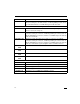
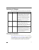
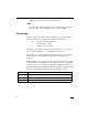
Summary of Changes
The following changes were made for the 4th revision of this manual.
Overview of Contents
The following paragraphs briefly describe the contents of each chapter.
Chapter 1, Hardware Preparation and Installation, provides a description
of the MVME5100 and its main integrated PMC and IPMC boards. The
remainder of the chapter includes an explanation of the installation
procedure, including preparation and jumper setting information.
Date Doc. Rev Changes
08/2001 V5100A/IH2 A correction was made on page 1-5 to change the
explanation of the jumper settings for Flash Bank A
and B. Flash Bank B (0) is the factory setting.
Memory Map information was also added to
Chapter 6, Programming Information. Appendix
B, Specifications was updated, and Appendix D,
RAM500 Memory Expansion Module was added.
Other corrections were made throughout the
manual. This section titled "About this Manual"
was also added.
02/2003 V5100A/IH3 Changes were made to pages 1-4 and 5-2
respectively to clarify the explanation for J16 to
state that the setting of jumpers 2 and 3 only write
protect the upper 64KB of Flash memory.
Additional corrections were made to Table 5-15 to
duplicate information in Rows Z and D from Table
5-14 and to add note below Table 5-15.
07/2003 V5100A/IH4 Changes were made to this section to update model
numbers and descriptions to coincide with the
MVME5100 Datasheet. Changes were also made to
correct the address of the DS1621 from $A6 to $96.
Changes were also made to specifications for
additional power ratings and additions were made
to a new thermal rating chart.