
user manual


2-1
2
2Operation
Introduction
This chapter provides operating instructions for the MVME5100 Single
Board Computer. It includes necessary information about powering up the
system along with the functionality of the switches, status indicators, and
I/O ports on the front panels of the board.
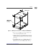
Switches and Indicators
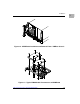
The front panel of the MVME5100 as shown in Figure 1-1, incorporates
one dual function toggle switch
(ABT/RST) and two Light-Emitting Diode
(LED) status indicators (
BFL, CPU) located on the front panel.
ABT/RST Switch
The ABT/RST switch operates in the following manner: if pressed for less
than 5 seconds, the
ABORT function is selected, if pressed for more than 5
seconds, the
RESET function is selected. Each function is described below.
Abort Function
When toggled to
ABT, the switch generates an interrupt signal to the
processor. The interrupt is normally used to abort program execution and
return control to the debugger firmware located in the processor and flash
memory.
The interrupt signal reaches the processor via ISA bus interrupt line IRQ8.
The interrupter connected to the
ABORT switch is an edge-sensitive circuit,
filtered to remove switch bounce.
Reset Function
When toggled to
RST, the switch resets all onboard devices. To generate a
reset, the switch must be depressed for more than five seconds.