
User's Manual


PrPMC800/800ET Processor PMC Module Installation and Use (PrPMC800A/IH5)
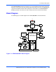
3 Functional Description
18
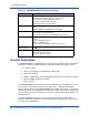
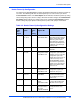
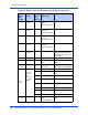
XAD[23] Jumper J2
pins 7-8
1 Generic power up
status bit 3
XCSR.GCSR.PUST
3
Software readable header bit
3
XAD[22] Jumper J2
pins 5-6
1 Generic power up
status bit 2
XCSR.GCSR.PUST
2
Software readable header bit
2
XAD[21] Jumper J2
pins 3-4
1 Generic power up
status bit 1
XCSR.GCSR.PUST
1
Software readable header bit
1
XAD[20] Jumper J2
pins 1-2
1 Generic power up
status bit 0
XCSR.GCSR.PUST
0
Software readable header bit
0
XAD[19] Jumper J2
pins 13-14
0 I2O IOP agent Set PCI Configuration register
CLAS to present class code
for “bridge device” (0) or “I2O
Controller” (1)
XAD[18] Fixed 0 Internal PCI arbiter Disable internal PCI arbiter
XAD[17] Fixed 1 Internal processor
arbiter
Enable internal Processor
arbiter
XAD
[16:15]
Fixed 00 XCSR register group
base address
Set XCSR register group
base address to $FEFF0000
XAD
[14-12]
On board
logic sets
ratio
depending
on state of
M66EN
000 reserved
001 3:2 Set PPC-to-PCI clock ratio to
3:2
010 2:1 Set PPC-to-PCI clock ratio to
2:1
011 5:2 Set PPC-to-PCI clock ratio to
5:2
100 1:1 Set PPC-to-PCI clock ratio to
1:1
101 reserved
110 3:1 Set PPC-to-PCI clock ratio to
3:1
111 reserved
XAD
[11:10]
Fixed 01 Xport channel 0 data
width
XCSR.XPAT0.DW
Set flash bank A to 16-bit
width
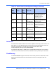
Table 3-2. Harrier Power-Up Configuration Settings (continued)
Harrier
XAD
Bus
Signal
Select
Option
Default
Power-
Up
Setting
Function/
Register Bit
Description