
User's Manual


PrPMC800/800ET Processor PMC Module Installation and Use (PrPMC800A/IH5)
3 Functional Description
22
Watchdog Timers
The Harrier ASIC contains two Watchdog timers, WDT0 and WDT1. Each timer is functionally
equivalent but independent. These timers continuously decrement until they reach a count of 0
or are reloaded by software. The time-out period is programmable from 1 microsecond up to 32
minutes. If the timer count reaches 0, a timer output signal is asserted. The output of Watchdog
Timer 0 is routed to an MPIC interrupt. The output of Watchdog Timer 1 is connected to the
Harrier AUXRST, which will generate RESETOUT_L.
Following a Harrier device reset, WDT0 is enabled with a default time-out of 8 seconds and
WDT 1is enabled with a default time-out of 16 seconds. Each timer must be disabled or
reloaded by software to prevent a time-out. Software may reload a new timer value or force the
timer to reload a previously loaded value. To disable or load/reload a timer requires a two step
process.
Interrupt Routing and Generation
External interrupts routed to the Harrier MPIC include the four PCI interrupts INTA#-INTD#, four
host board interrupts from PMC connector P14, and the output from the watchdog timers. The
PrPMC800/800ET has the ability to generate any one of the PCI interrupts INTA#-INTD# by
using the Harrier Generic Outbound Doorbell register or the I2O controller. The desired PCI
interrupt is selected by programming the PCI Interrupt Mapping bits in the Harrier Bridge PCI
Control and Status register.
Asynchronous Serial Port
The PrPMC800/800ET module provides a two-wire asynchronous serial interface (TXD and
RXD) for use as a serial debug port. UART0 in the Harrier ASIC provides the 16550 compatible
UART controller. The UART0 port SIN0 and SOUT0 signals are wired to an external RS-232
transceiver which interfaces to the 2mm debug header and the P14 connector. An onboard
1.8432 MHz oscillator provides the baud rate clock for the UART.
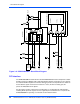
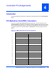
Clock Generator
The PrPMC800/800ET module clock generator uses a Z9972 PLL clock driver to provide the
clocks for the processor, the Harrier ASIC and the SDRAMs. All clocks are referenced to the
PCI clock input on PMC connector P11. The PrPMC800/800ET supports the PPC-to-PCI clock
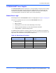
ratios listed in the following table. Onboard logic uses the state of the PMC M66EN pin to
determine whether the maximum PCI clock frequency will be 33 MHz or 66 MHz.
Table 3-3. PPC to PCI Clock Ratios
M66EN Pin PPC Clock
Frequency
(MHz)
PCI Clock
Frequency
(MHz)
Ratio
(PPC:PCI)
Harrier PCI
Clock Divisor
(N)
Low 100 33.33 3:1 12
High 100 66.67 3:2 6