
- MOTOROLA power supply user guide PTP 400 Series

33
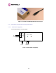
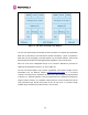
The connection between the PTP 400 Series Bridge PIDU Plus and the user’s equipment can
be made using any standard CAT5 patch cable. The RJ45 Ethernet connection is presented
as a piece of network equipment. However as automatic MDI/MDI-X sensing and pair
swapping is employed a crossed Ethernet patch cable can be used for connection to another
piece of networking equipment or directly to end user equipment.
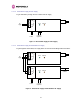
It should be noted that the PIDU Plus provides continuity between the screen on the ODU to
PIDU Plus cable and screen on the PIDU Plus-User equipment cable. If continuity of the
screening is desired from the ODU to the PIDU Plus to the user’s equipment, CAT5 STP
cable and connectors should be used for the latter connection. CAT5 STP cable between the
PIDU Plus and the user’s equipment will provide additional protection against surges induced
on the Ethernet connections.
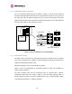
3.3.6 Surge Arrestor
The PTP 400 Series Bridge PIDU Plus does not provide lightning or surge suppression.
Should lightning or surge suppression be required a separate Ethernet surge suppressor
should be used and appropriately earthed. Suitable surge suppressors can be sourced from
your Motorola Point-to-Point Distributor or Solutions Provider. The ODU is protected by built-
in surge suppression as standard. See
11 “Lightning Protection”.
3.3.7 Mounting Brackets
The PTP 400 Series Bridge is supplied with a mounting bracket suitable for mounting the
ODU to a pole of 25mm (1”) to 75mm (3”) in diameter. For more details on mounting, see
section
7 “Installation”.
The bracket allows for adjustment in both azimuth and elevation.
The PIDU Plus can either be desk or wall mounted. The preference is wall mounted with the
cables dressed to a cable channel. Remember to leave space for access to the recovery
button. See section
7.7.6.