M RFS6000 Series RF Switch Installation Guide
MOTOROLA and the Stylized M Logo are registered in the US Patent & Trademark Office. Symbol is a registered trademark of Symbol Technologies, Inc. All other product or service names are the property of their respective owners. © Motorola, Inc. 2008. All rights reserved.
Contents 1.0 Introduction . . . . . . . . . . . . . . . . . . . . . . . . . . . . . . . . . . . . . . . . . 1 2.0 Specifications . . . . . . . . . . . . . . . . . . . . . . . . . . . . . . . . . . . . . . . 3 3.0 LED Codes . . . . . . . . . . . . . . . . . . . . . . . . . . . . . . . . . . . . . . . . . . . 4 4.0 Hardware Setup. . . . . . . . . . . . . . . . . . . . . . . . . . . . . . . . . . . . . 11 5.0 Regulatory Information . . . . . . . . . . . . . . . . . . . . . . . . . . . . . . . 20 6.
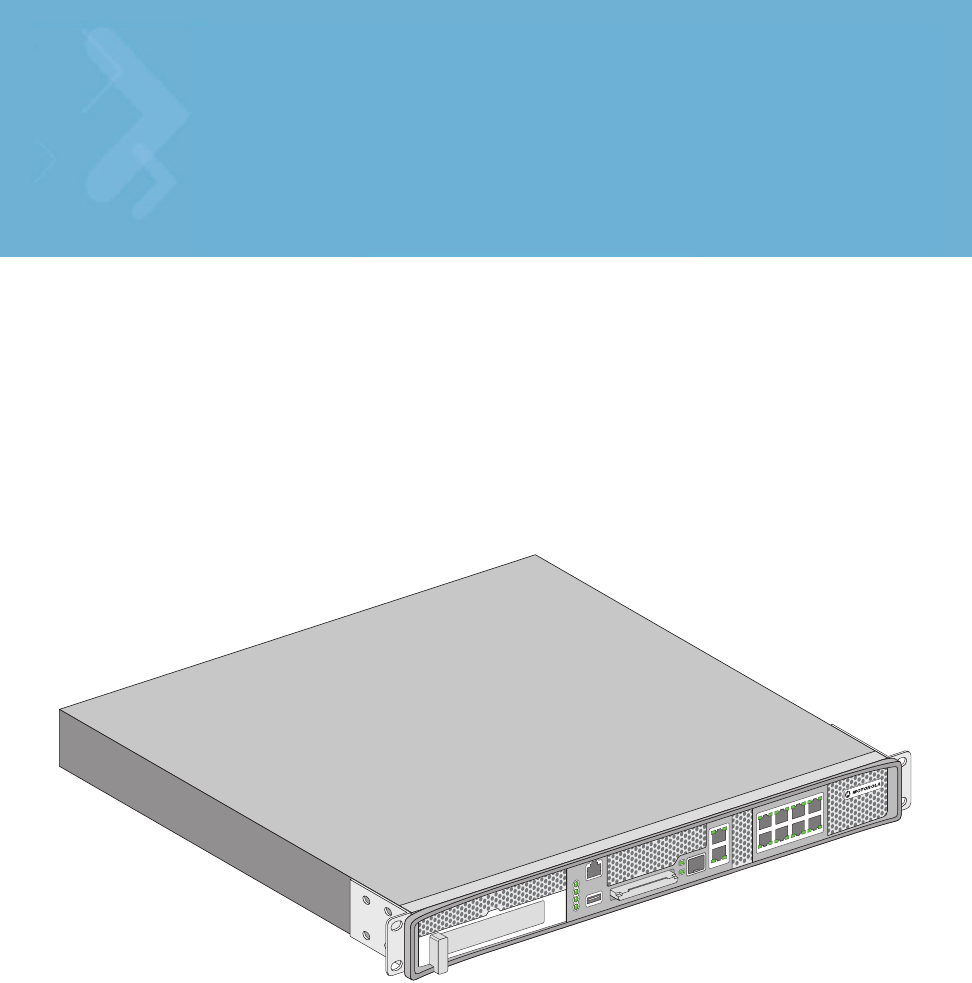
Introduction 1 Introduction The Motorola RFS6000 Series RF Switch is a high-performance member of Motorola’s Wireless Switch family. The RFS6000 Series RF Switch provides centralized Wireless LAN (WLAN) configuration and management by coalescing a network “intelligence” previously spread across physically distributed access points.
Introduction 1.3 Warnings • • • • • • • • • • • • • • Read all installation instructions and site survey reports, and verify correct equipment installation before connecting the system to its power source. Remove jewelry and watches before installing this equipment. Install the equipment in a rack with adequate dimensions and weight allowances. Verify the rack is anchored and cannot tip over or break away from its mountings. Verify the unit is grounded before connecting it to the power source.
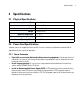
Specifications 2 Specifications 2.1 Physical Specifications Width 440mm (17.32 in) Height 44.45mm (1.75 in) Depth 390.8mm (15.38 in) Weight Operating Temperature Operating Humidity Operating Altitude 6.35 Kg (14.0 lbs) 0°C - 40°C 5% - 85% RH, non-condensing 3 km (10000 ft) 2.2 Power Cord Specifications A power cord is not supplied with the switch. Use only a correctly rated power cord certified (as appropriate) for the country of operation. 2.2.
LED Codes 3 LED Codes The RFS6010 RF Switch has four vertically-stacked LEDs on its front panel. Each of the switch’s Gigabit Ethernet ports have two status LEDs. These LEDs display two colors (green & amber), and three lit states (solid, blinking, and off). The following tables decode the combinations of LED colors and states for the System Status LEDs and the Gigabit Ethernet LEDs. 3.
LED Codes 3.1.
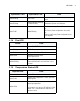
LED Codes System Status 1 LED System Status 2 LED Event Green Blinking Green Solid Redundant System failed over and adopting ports Green Blinking Alternating Green Blinking & Amber Blinking Redundant System not failed over. Amber Blinking No License to adopt Access Ports or No Country Code configured on the switch or License and Country Code configured, but no APs adopted Green Solid 3.1.
LED Codes Temperature LED Amber Blinking Event Ambient Inlet Temperature is above the maximum specified operating temperature System will be held in reset until the issue is resolved 7
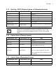
LED Codes 3.2 RJ-45 Gigabit Ethernet LEDs Port speed 3.2.1 Port activity RJ-45 Port Speed LED Port Speed LED Event Off 10 Mbps Green Solid 100 Mbps Amber Solid 1000 Mbps 3.2.
LED Codes 3.3 SFP Gigabit Ethernet LEDs Port speed Port activity 3.3.1 SFP Port Speed LED Port Speed LED Amber Solid 3.3.
LED Codes 3.4 Management Port LEDs Port speed Port activity Management port 3.4.1 Out of Band Management Port Speed LED Port Speed LED Event Off 10 Mbps Green Solid 100 Mbps 3.
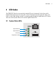
Hardware Setup 4 Hardware Setup Out-of-band management Console USB ExpressCard PoE enabled gigabit ethernet ports 1, 3, 5, 7 Ports 2, 4, 6, 8 UPLINK 4.1 Cabling Information Out-of-band management port Console connector ExpressCard UPLINK Gigabit Ethernet RJ-45 connectors with per-port LEDs and PoE USB port The RFS6010 RF Switch has nine RJ-45 Gigabit Ethernet ports, one Gigabit SFP (fiber) port, one Outof-band management port and one Console connector.
Hardware Setup expansion. For software configuration, please see the Motorola RF Switch System Reference available from the Motorola website. 4.2 Gigabit Ethernet on the RFS6010 RF Switch System LEDs: System Status 1 System Status 2 Fan Status Temperature Status Out-of-band management port Console connector UPLINK USB port Gigabit Ethernet RJ-45 connectors with per-port LEDs ExpressCard The RFS6010 RF Switch has nine RJ-45 Gigabit Ethernet ports and one Gigabit SFP (fiber optic) port.
Hardware Setup 4.2.1 Installing the Gigabit Ethernet SFP 1. Open the bail on the transceiver. Open bail to insert or remove SFP transceiver 2. Insert the SFP transceiver into the corresponding port on the switch. 3. Once the SFP transceiver is properly seated in the port, close the bail to lock the transceiver in place.
Hardware Setup 4. Insert the fiber optic cables into the installed transceiver.
Hardware Setup 4.3 Connecting USB Devices USB port The RFS6010 RF Switch contains one USB port for connecting USB flash storage devices to the switch. The switch can use the USB flash storage device for file and log transfers. Follow the setup instructions below to connect the devices to the switch and then access those devices through the Web UI or Command Line Interface. 1. Connect the USB flash drive to the USB . 2. Wait a few seconds for the drive to be recognized by the switch. 3.
Hardware Setup 4.4 Rack Mount Instructions To install the RFS6000 Series RF Switch in a rack: 1. The rack mounting brackets are installed at the factory. No additional steps are needed. 2. Attach the brackets to the rack using screws appropriate for your rack’s mounting holes.
Hardware Setup 4.5 RFS6000 Series RF Switch Console Port Setup To add the RFS6000 Series RF Switch to the network and prepare it for initial configuration: 1. Using the supplied console cable (pictured below), connect the RFS6000 Series RF Switch serial port to an RS-232 (DB-9) serial port on a separate computer (the “configuration computer”). 2.
Hardware Setup 4.6 Supplying Power to the RFS6000 Series RF Switch AC inlet Rack mount bracket 1. Plug an approved AC power cord into the power connector at the back of the RFS6000 Series RF Switch. 2. Plug the cord into a standard AC outlet with a voltage range of 100 to 240 VAC. . WARNING! An improper shutdown can render the RFS6000 Series RF Switch inoperable such that it could require service by Motorola Support. Do not remove AC power without first following the shutdown procedure.
Hardware Setup 4.7 Verifying the Installation View the LEDs on the front panel of the RFS6010 RF Switch to ensure the device is functioning properly. The normal LED pattern follows this path: • • • • During the Power On Self Test (POST), the System 1 and System 2 LEDs both blink green. If the POST test fails, the System 1 LED will blink amber. If the POST test succeeds, the System 1 LED will be lit solid green. As the software is initialized, the System 2 LED will blink green.
Regulatory Information 5 Regulatory Information This regulatory section applies to the RFS-6010. For more information refer to section 6, Part Numbers, Support, and Sales. All Motorola devices are designed to be compliant with rules and regulations in locations they are sold and will be labeled as required. Any changes or modifications to Motorola equipment, not expressly approved by Motorola, could void the user’s authority to operate the equipment.
Regulatory Information Cet appareil numérique de la classe A est conforme à la norme NMB-003 du Canada.. Marking and European Economic Area (EEA) ! CAUTION This is a class A product. In a domestic environment this product may cause radio interference in which case the user may be required to take adequate measures. Statement of Compliance Motorola hereby declares that this device is in compliance with all the applicable Directives, 2004/108/EC, 2006/95/EC.
Regulatory Information Waste Electrical and Electronic Equipment (WEEE) English: For EU Customers: All products at the end of their life must be returned to Symbol for recycling. For information on how to return product, please go to: http://www.symbol.com/environmental_compliance. Dansk: Til kunder i EU: Alle produkter skal returneres til Symbol til recirkulering, når de er udtjent. Læs oplysningerne om returnering af produkter på: http://www.symbol.com/ environmental_compliance.
Regulatory Information Italiano: per i clienti dell'UE: tutti i prodotti che sono giunti al termine del rispettivo ciclo di vita devono essere restituiti a Symbol al fine di consentirne il riciclaggio. Per informazioni sulle modalità di restituzione, visitare il seguente sito Web: http://www.symbol.com/ environmental_compliance. Magyar: Az EU-ban vásárlóknak: Minden tönkrement terméket a Symbol vállalathoz kell eljuttatni újrahasznosítás céljából.
Part Numbers, Support, and Sales 6 Part Numbers, Support, and Sales Part Numbers Description Part Number RFS6010 WITH ZERO PORTS RFS-6010-100R0-WR RFS6010 WITH 8 PORTS RFS-6010-10010-WR RFS6010 WITH 24 PORTS RFS-6010-10030-WR RFS6010 WITH 48 PORTS RFS-6010-10060-WR 8 PORT-RFS6000 SERIES UPGRADE CERTIFICATE RFS-6010-UC-08-WR Motorola’s Enterprise Mobility Support Center If you have a problem with your equipment, contact Enterprise Mobility support for your region.
Motorola, Inc. End-User License Agreement 7 Motorola, Inc. End-User License Agreement BY DOWNLOADING, INSTALLING, OR USING THE SOFTWARE DESCRIBED IN THIS DOCUMENT, YOU OR THE ENTITY OR COMPANY THAT YOU REPRESENT ("LICENSEE") ARE UNCONDITIONALLY CONSENTING TO BE BOUND BY AND ARE BECOMING A PARTY TO THIS LICENSE AGREEMENT ("AGREEMENT"). LICENSEE'S USE OR CONTINUED USE OF THE DOWNLOADED OR INSTALLED MATERIALS SHALL ALSO CONSTITUTE ASSENT TO THE TERMS OF THIS AGREEMENT.
Motorola, Inc. End-User License Agreement interrupt, destroy or limit the functionality of any computer software or hardware or telecommunications equipment. Licensee, not Licensor, remains solely responsible for all Content that Licensee uploads, posts, e-mails, transmits, or otherwise disseminates using, or in connection with, the Software. 4 FEES; SUPPORT AND UPGRADES. Licensor may, at Licensor's sole option, provide support services related to the Software ("Support Services").
Motorola, Inc. End-User License Agreement 9 INDEMNITY. Licensee agrees that Licensor shall have no liability whatsoever for any use Licensee makes of the Software. Licensee shall indemnify and hold harmless Licensor from any claims, damages, liabilities, costs and fees (including reasonable attorney fees) arising from Licensee's use of the Software as well as from Licensee's failure to comply with any term of this Agreement. 10 FAULT TOLERANCE.
Motorola, Inc.
Motorola, Inc.
Motorola, Inc.
Motorola, Inc.
MOTOROLA INC. 1303 E. ALGONQUIN ROAD SCHAUMBURG, IL 60196 http://www.motorola.