
Personal Computer User Manual


5-28 Computer Group Literature Center Web Site
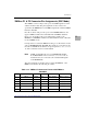
Pin Assignments
5
Note Since the P2 adaptor card for the MVmE712M is a three (3)
row connector, signals on Rows Z and D are not routed to the
MVME712M. Thus
(a) although the IPMC712 controller is capable of 16-bit
(wide) SCSI operations only 8-bit (narrow) transfers are
supported through the MVME712M
(b) PMC I/O from site two (2) is not available through the
MVME712M
(c) Please remember the caution stated on page 5-25 that a
PMC located at site two (2) may not connect to pins J24-2, 5,
8, 11, 14, 17, 20, 23 and 26.
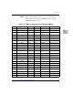
25 PMC2_38 (J24-38) TXD4 VD26 RTS1 PMC2_37 (J24-37)
26 GND RXD4 VD27 CTS1 PMC2_39 (J24-39)
27 PMC2_41 (J24-41) RTS4 VD28 TXD2 PMC2_40 (J24-40)
28 GND TRXC4 VD29 RXD2 PMC2_42 (J24-42)
29 PMC2_44 (J24-44) CTS4 VD30 RTS2 PMC2_43 (J24-43)
30 GND DTR4 VD31 CTS2 PMC2_45 (J24-45)
31 PMC2_46 (J24-46) DCD4 GND DTR2 GND
32 GND RTXC4 +5V DCD2 VPC
Table 5-15. VMEbus Connector P2 Pinout with IPMC712 (Continued)
Pin Row Z Row A Row B Row C Row D