Operator’s Guide DOCSIS® 3.
About This Document This document provides instructions on installation and connection of cables and wiring for the M-eMTA device only. Cabling to the facility or external networks are not covered here. Motorola Part Number: 558005-002-z1 February 2010 Copyright © 2010 Motorola, Inc. All rights reserved.
Safety Information Caution These servicing instructions are for use by qualified personnel only. To reduce the risk of electrical shock, do not perform any servicing other than that contained in the Installation and Troubleshooting Instructions unless you are qualified to do so. Refer all servicing to qualified service personnel. Special Symbols That Might Appear On the Equipment This symbol indicates that dangerous voltage levels are present within the equipment.
Regulatory Information FCC Compliance This device complies with part 15 of the FCC Rules. Operation is subject to the following two conditions: (1) This device may not cause harmful interference, and (2) this device must accept any interference received, including interference that may cause undesired operation. Note that this equipment has been tested and found to comply with the limits for a Class B digital device, pursuant to part 15 of the FCC Rules.
Caring For the Environment by Recycling When you see the following symbol on a Motorola product, do not dispose of the product with residential or commercial waste. Recycling Your Motorola Equipment Please do not dispose of this product with your residential or commercial waste. Some countries or regions, such as the European Union, have set up systems to collect and recycle electrical and electronic waste items. Contact your local authorities for information about practices established for your region.
vi M-eMTA Installation Guide
Table of Contents Chapter 1 Introduction .................................................................................................................................. 1 Intended Audience ..................................................................................................................... 1 Contact Information.................................................................................................................... 1 SBV5506 Chassis Overview .....................................
Connecting the AC Facility Power Source (Power Cable to Indoor 120 VAC Outlet) ......... 20 Connecting the Power and Jumper Cables (Indoor Configuration Only) ....................... 20 Connecting the AC HFC Power Source ............................................................................. 23 Connecting the M-eMTA From the HFC Plant ............................................................... 23 Connecting the UPS DC Power Source....................................................................
Chapter 1 Introduction This document provides installation and cabling instructions for the M-eMTA device, not cabling to the facility or external networks.
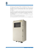
Each chassis consists of the assembly to hold the blades, the input connection for the Hybrid Fiber/Coax (HFC) RF connector, the input power connections, the output telephone connections, and the high-speed data connections. The backplane has 6-layer construction, contains RF, telephone, Ethernet, power signals, and a ground plane. The chassis also incorporates an RF signal switching system that terminates the RF signal into a load whenever there is no blade in a slot.
Chassis Components This section provides an overview of the SBV5506 chassis components.
Backplane Components The following illustration provides an overview of the SBV5506 backplane components.
Key Component Name 11 Right AC Surge Protector (SP2) 12 Ground Assembly 13 F–Connector 14 UPS DC Terminal Block 15 UPS DC Surge Protector (SP3) 16 Fuse (F3) 17 Telephone Line RJ–21 Connector Rear Chassis Components The following illustration provides an overview of the SBV5506 rear chassis components. SBV5506 Backplane Chapter 1: Introduction Component Name 1. Mounting Flange 2. Heat Sink 3.
Wall Bracket Components The following illustration provides an overview of the SBV5506 wall bracket components. Wall Bracket Component Name 1. Wall mounting holes 2. Cleat Slots Conduit/Cable Grip Components Perform a visual check of the cabling conduits installed on the bottom of the SBV5506 chassis. Use the diagram and chart below to verify proper installation of the conduits. Conduit/Cable Grips 6 Component Name 1. #1 Conduit/cable grips – All-power cables (AC or DC) and ground cable. 2.
M-eMTA Component Overview Descriptions This section provides an overview of the M-eMTA components. Power Supply The chassis can accept a nominal input of 90 VAC (70 VAC lower limit) from the HFC network, +12VDC UPS power, or up to 120 VAC from facility power: • HFC Network Power – Power source is derived from the normal HFC 90 VAC power on the cable plant and is extracted for M-eMTA use with a readily available power tap with a Siamese twisted pair power output.
Blades The 2-line blade is based on Motorola’s SURFboard SBV5222 digital voice modem, while the 4-line blade is based on Motorola’s SURFboard SBV5322 digital voice modem. NOTE: The 2-port and 4-port blades are also available with a diagnostic port (optional). eMTA Module Number # of Lines # of Subscribers SBV5622 2 1 or 2* SBV5642 4 1 to 4* * Dependent on the provisioning capabilities of the Multiple System Operator (MSO). The following illustration provides an overview of the blade components.
Hot Swappable and Field Replaceable Chassis Components The blades and the power supply modules are hot swappable, and the following components are field replaceable: • Blades • Power supply modules • Surge protectors (SP1, SP2, and SP3) • Fuses (F1, F2, and F3) Optional Accessories Order the items listed below to aid in M-eMTA installation: • AC power cable kit – Use the 110 V power cable for AC facility connections. • RJ-21 cable kit – Use the cable to quickly connect telephony features.
10 M-eMTA Installation Guide
Chapter 2 Pre-Installation Before you begin the M-eMTA hardware installation, make sure that you have the required tools and equipment and that you have identified the proper location to mount the SBV5506 chassis. Pre-Installation Checklist The following hardware, tools, cables, and wiring are required for the M-eMTA installation. Hardware Note that the chassis are shipped without the power supplies and blades installed.
Cables and Wiring The following cables and wiring are required for the M-eMTA installation: • Coaxial cable – RG6 or RG59 diameter cable. • HFC powering cable – 18 to 22 AWG (0.8 to 0.6438 mm2 cross-sectional area – twisted pair). Note that this cable is only used for the HFC powering option. • AC powering cable – See “Connecting the AC Facility Power Source (Power Cable to Indoor 120 VAC Outlet)” on page 20. Note that this cable is only used for the AC powering option.
Chapter 3 Hardware Installation This chapter provides information for installing the M-eMTA hardware. Cabling the M-eMTA is easier when placed on a flat level surface. When possible, Motorola recommends making the connections inside the box prior to permanently mounting the chassis.
Connect the Grounding Wire The SBV5506 chassis must be grounded to the facility. Select the grounding instruction applicable to the corresponding powering option. WARNING: Review the following safety precautions before installing the unit: • Improper grounding may damage the M-eMTA. Refer to National Electrical Code (NEC) guidelines and/or local regulations for the M-eMTA grounding to the building grounding system.
6. Thread the AC power cable downward through the first opening on the Cable Strain Relief Bracket. 7. Wrap the excess cable around the Cable Strain Relief Bracket. 8. Remove approximately a ½” of insulation from the green ground wire to expose the copper. 9. Insert the ground wire (from the right) into the bottom of the grounding terminal. 10. Tighten the grounding terminal to secure the wire. for more information, see “Securing the Cables” on page 31.
Punch-Down Terminal Follow these steps to connect the punch down terminal: 1. Insert telephone cables through the #3 coupling. 2. Lift the first punch down terminal. 3. Insert the individual strands (Tip = green, Ring = red). 4. Return the punch down terminal to the down position. 5. Repeat steps 1–4 for additional phone lines. 6. Secure the telephone lines with a cable tie. For more information, see “Securing the Cables” on page 31.
Connect the Power Cables CAUTION: Although different power configurations are available, only one powering option can be used at a time. When servicing requires the equipment to be powered down, make sure all power sources have been disconnected. Depending on your situation, there are three options available for supplying power to the SBV5506 chassis.
Connecting the AC Facility Power Source (Hardwire) CAUTION: USE only one powering option at a time. • To avoid personal injury, follow the NEC guidelines and/or local regulations during the installation. When using the facility power, the SBV5506 should be connected to a 20-amp branch circuit that is part of the building installation. A licensed electrician may be required to make this connection. Wire the power cables to the SBV5506 before making connection to the facility power.
5. Connect the other end of each jumper cable to the AC2 terminal block. NOTE: Hot [black] = screw 1, neutral [white] = screw 3. 6. Secure the power cable using the strain relief bushing. For more information, see “Securing the Cables” on page 31. Note that any cabling outside the interior of the premise should be contained inside a conduit. WARNING: You must put on an Electrostatic Discharge (ESD) wristband before continuing. 7.
Connecting the AC Facility Power Source (Power Cable to Indoor 120 VAC Outlet) CAUTION: Use only one powering option at a time. • To avoid personal injury, follow the NEC guidelines and/or local regulations during the installation. Only use power cables that meet the NEC guidelines and/or local regulations. When using the facility power, the SBV5506 should be connected to a 20 amp branch circuit that is part of the building installation. A licensed electrician may be required to make this connection.
4. Connect the power cables and one end of the jumper cables to the AC1 terminal block. NOTE: Place the flats of the wires back-to-back before inserting the screw. Hot cables [black] = screw 1, neutral cables [white] = screw 3. 5. Connect the other end of each jumper cable to the AC2 terminal block. NOTE: Hot [black] = screw 1, neutral [white] = screw 3.
6. Secure the cables using the bushing. For more information, see “Securing the Cables” on page 31. WARNING: You must put on an Electrostatic Discharge (ESD) wristband before continuing. 7. Slide the AC power supply modules (left and right) into the power supply enclosure area. 8. Insert the blade(s) into the chassis. For more information, see “Installing the Blades” on page 29. 9. Reattach the protective shields over the AC1 and AC2 terminal blocks. 10. Place the chassis onto the wall mount bracket.
Connecting the AC HFC Power Source CAUTION: The M-eMTA accepts an HFC network voltage of 70 to 90 VAC. Before installing, verify that the HFC network voltage is within this range. • • • • Disconnect the power at the tap before performing this procedure. To turn the unit on and off; the power cables connecting the unit to the HFC network power source acts as the disconnect device. Use only one powering option at a time.
6. Secure the power cables using the cable strain relief bracket. For more information, see “Securing the Cables” on page 31. WARNING: You must put on an Electrostatic Discharge (ESD) wristband before continuing. 7. Slide the AC power supply modules (left and right) into the power supply enclosure area. 8. Insert the blade(s) into the chassis. For more information, see “Installing the Blades” on page 29. 9. Reattach the protective shields over the AC1 and AC2 terminal blocks. 10.
Connecting the UPS DC Power Source CAUTION: Ensure that the UPS DC power source is not powered. • • • • • To avoid personal injury, use the NEC guidelines during the installation. To turn the unit on and off; the power cables connecting the unit to the UPS DC power source acts as the disconnect device. Do not use the power supply modules with this option. Use only one powering option at a time. Use an ESD wrist band during the installation. Follow these steps to connect the UPS DC power source: 1.
9. Insert the blade(s) into the chassis. For more information, see “Installing the Blades” on page 29. 10. Reattach the protective shields over the terminal blocks. 11. Place the chassis onto the wall mount bracket. For more information, see “Mounting the Chassis Onto the Wall Bracket” on page 29. 12. Connect the UPS to the power source to activate the UPS +12 VDC output. 13.
NOTE: For a cinder block installation, use a screwdriver to tighten the anchors. If Mounting To... Cinder Block Then Use This Hardware (4) ¼”- 20 hollow wall anchors (4) ¼”- 20 machine screws (4) ¼” flat washers Brick and Concrete (4) ¼” expansion anchors (4) ¼” x 2” lag screws (4) ¼” flat washers Siding (4) ¼” x 3” lag screws (4) ¼” flat washers Wood (4) ¼” x 2” Wood screws (4) ¼” flat washers Wall Bracket Installation Follow these steps to mount the wall bracket: 1.
5. Drill the pilot holes. (Skip this step if the surface is wood.) NOTE: Due to the expansion and contraction of vinyl and aluminum siding during changes in temperature most manufacturers recommend drilling mounting holes larger than the screw or bolt diameter. Please consult the siding manufacturer for specific information. Do not over tighten the lag screws on vinyl siding since this prevents free movement when expansion occurs.
Mounting the Chassis Onto the Wall Bracket Prior to mounting the SBV5506 chassis onto the wall bracket, verify the following: • Wall bracket is securely attached to the structure. • Pilot holes for the Mounting Flange on the chassis have been drilled. (Unless the surface is wood.) • Panel fasteners around the perimeter of the chassis door are engaged to prevent the door from opening during the installation. Follow these steps to mount the chassis onto the wall bracket: 1.
3. Insert the blade into the first slot in the SBV5506 chassis. 4. Push the blade into place using the ejector handles. 5. Lock the blade into place by pressing the top handle down and the bottom handle up. Push to lock 6. Repeat steps 1–5 to install additional blades.
Securing the Cables After the SBV5606 chassis has been mounted on the wall, installers must secure all cables in the M-eMTA using the cable strain relief bracket. Follow the steps below to secure the telephone cables, data cables, RF cables, and power cables for UPS connections.
NOTE: Space the cable ties approximately 2 inches from each other. Do not fully tighten the bundle cable ties. 6. Feed the secured cable tie through the bundle cable ties and tighten. 7. Trim the excess material from the cable ties using wire cutter. Securing the Chassis After completing the installation, close the door, torque the panel fasteners to 20 in-lbs., and insert and close a lock in the padlock slot on the door.
Chapter 4 Troubleshooting This section provides basic solutions for problems that installers might encounter. For additional assistance, please contact Motorola Technical Support for a complete copy of the latest Motorola eMTA Troubleshooting Guide. Description of the Problem Solution POWER The LEDs on the power supply module and/or the Blade(s) are not on. • • • The LEDs indicate abnormal on the power supply module and/or the blade(s): • • Verify that the HFC Power is properly connected.
Description of the Problem Solution TELEPHONE • • Telephone lines are not provisioned as indicated by blade indicators. Blade telephone indicators are normal, but the telephone functions are not operational. • • Verify the provisioning server is working properly. Verify the telephone test ports and backplane wiring. DATA • • Blade link line indicator is not on. No connectivity. • • Verify the Ethernet connection(s) on the backplane. Ping 192.168.100.1 using an Ethernet connection on the backplane.
Appendix A Technical Specifications The M-eMTA has the following technical specifications. Note that these specifications are subject to change without notice. General Specifications Cable Interface F–connector, female, 75 Ω Network Interface 10/100 Ethernet Data Protocol TCP/IP Dimensions (6–slot chassis) 22”H x 10.5”D x 12”W Weight (6–slot chassis) Approximately 24 pounds (Approximately 36 pounds if fully populated.
Downstream Modulation 64 or 256 QAM Max. Data Rate* 38 Mbps (256 QAM at 5.361 Msym/s) Bandwidth 6 MHz Symbol Rates 64 QAM 5.069 Msym/s 256 QAM 5.361 Msym/s Operating Level Range -15 to +15 dBmV Frequency Range 88 to 860 MHz (edge to edge) Input Impedance 75 Ω (nominal) *. When comparing download speeds with a traditional 28.8k analog modem. Actual speeds will vary, and are often less than the maximum possible.
Software SIP* Support Session Initiation Protocol (SIP) NCS* Support Network Call Signaling (NCS) *. SBV56xx modules will support either SIP OR NCS, not both at the same time. Data 6 Data Ports for SBV5506 10/100 Ethernet MoCA-Powering on Power Over Ethernet (POE)* *. The maximum loading for each of the (6) data ports MoCA powering (POE) should not exceed 3W (18W total).
Telephony Line Type 2-wire Hook State Signaling Loop start Maximum Loop Length 1000 ft (AWG 26/0.4 mm @ 65 °C) DTMF Level Sensitivity Range 0 to -20 dBm Speech Coding 64 kbps PCM, μ-law or A-law companding; supports G.711 and other low-rate vocoders. Line Termination Configurable based on market needs. Loss Plan Receive (D/A) 4 dB; transmit (A/D) 2 dB (configurable based on market needs).
Motorola, Inc. 101 Tournament Drive Horsham, PA 19044 USA http://www.motorola.com MOTOROLA and the stylized M logo are registered in the US Patent and Trademark office. All other product and service names are the property of their respective owners. Copyright © 2010 Motorola, Inc. All rights reserved. No part of this publication may be reproduced in any form or by any means or used to make any derivative work (such as translation, transformation, or adaptation) without written permission from Motorola, Inc.