
Installation guide


2 M-eMTA Installation Guide
Each chassis consists of the assembly to hold the blades, the input connection for
the Hybrid Fiber/Coax (HFC) RF connector, the input power connections, the out-
put telephone connections, and the high-speed data connections. The backplane
has 6-layer construction, contains RF, telephone, Ethernet, power signals, and a
ground plane.
The chassis also incorporates an RF signal switching system that terminates the
RF signal into a load whenever there is no blade in a slot. This system design
maintains the impedance seen by the blades in the M-eMTA to minimize reflec-
tions within the chassis. The one RF input to the SBV5506 splits to the six slots
on the back plane.
Both the downstream and upstream input levels are maintained using amplifiers
to achieve a near unity gain through the back panel.
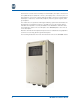
The following illustration shows the front and side views of the SBV5506 chassis.