
Installation guide


4 M-eMTA Installation Guide
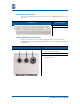
Backplane Components
The following illustration provides an overview of the SBV5506 backplane compo-
nents.
Key Component Name
1 Power Supply Enclosure Area
2 Upper Card Guide
3 Blade Enclosure Area
4Lower Card Guide
5 RJ–45 Ethernet Connectors
6 Telephone Line Punch Down Terminals
7 Fuses (F1 and F2)
8 Left AC Terminal Block (AC1)
9 Left AC Surge Protector (SP1)
10 Right AC Terminal Block (AC2)