
Installation guide


Chapter 1: Introduction 9
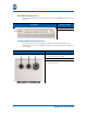
Hot Swappable and Field Replaceable Chassis Components
The blades and the power supply modules are hot swappable, and the following
components are field replaceable:
• Blades
• Power supply modules
• Surge protectors (SP1, SP2, and SP3)
• Fuses (F1, F2, and F3)
Optional Accessories
Order the items listed below to aid in M-eMTA installation:
• AC power cable kit – Use the 110 V power cable for AC facility con-
nections.
• RJ-21 cable kit – Use the cable to quickly connect telephony features.
• 100-pin external punch down block – Use with the RJ-21 cable to con-
nect additional telephone lines external to the M-eMTA.
Safety Precautions and Warnings
CAUTION: When working with the M-eMTA, be aware of the following
safety precautions and warnings:
• Only qualified service personnel should install this device.
• Improper grounding may damage the M-eMTA.
• Refer to National Electrical Code (NEC) guidelines and/or local regula-
tions for the M eMTA grounding to the building grounding system.
• Disconnect TNV circuit connector(s) before disconnecting power.
• The Motorola SURFboard M-eMTA accepts a maximum voltage of
120V. Because of the voltage levels, there is a risk of electrical shock.
Follow the NEC recommendations to avoid electric shock.
• In accordance with NEC 725 and 800, all output conductors routed
outside of the building are required to be less than 140 feet, and there
must be adequate clearance from power and lightning conductors.