
Installation guide


13
Chapter 3
Hardware Installation
This chapter provides information for installing the M-eMTA hardware. Cabling the M-eMTA is eas-
ier when placed on a flat level surface. When possible, Motorola recommends making the con-
nections inside the box prior to permanently mounting the chassis.
Overview
To complete the M-eMTA installation, you must perform the procedures in the fol-
lowing sections:
• Grounding and Cabling the Chassis, page 13
• Installing the Wall Bracket, page 26
• Mounting the Chassis Onto the Wall Bracket, page 29
• Installing the Power Supplies, page 29
• Installing the Blades, page 29
• Securing the Cables, page 31
• Securing the Chassis, page 32
Grounding and Cabling the Chassis
The following sections explain how to prevent personal injury or damage to the
product. Make connections to the M-eMTA device in the following sequence:
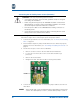
1. Connect the Grounding Wire, page 14
2. Connect the Telephone Cables, page 15
3. Connect the Data Cable(s), page 16
4. Connect the RF Cable, page 16
5. Connect the Power Cables, page 17
For an overview of the SBV5506 conduit and cable grips, see “Conduit/
Cable Grip Components” on page 6.
NOTE: