
Installation guide


14 M-eMTA Installation Guide
Connect the Grounding Wire
The SBV5506 chassis must be grounded to the facility. Select the grounding
instruction applicable to the corresponding powering option.
Grounding Instructions for AC Facility Power Source Options
Follow these grounding instructions:
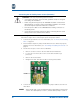
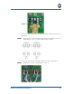
1. Open the chassis door using a Phillips or flathead screwdriver to loosen the
panel fasteners.
2. Loosen the dome nut on the conduit/cable grips.
3. Remove the protective shields covering the AC and UPS terminal blocks.
4. Loosen the grounding terminal using a flathead screwdriver.
5. Insert one AC power cable through conduit/cable grip #1.
Pull enough cable through the conduit to wrap around the cable strain
relief bracket (approximately 22”). Installers may need to place the AC
power cable into a ¾” conduit hose prior to cabling. Refer to NEC guide-
lines and/or local regulations.
WARNING: Review the following safety precautions before installing the
unit:
• Improper grounding may damage the M-eMTA. Refer to National Elec-
trical Code (NEC) guidelines and/or local regulations for the M-eMTA
grounding to the building grounding system.
• Ensuring that the customer has proper protective ground for the
SBV5506 is a safety, liability, and service related requirement. Many
ground scenarios are possible on the customer’s property. Install a 6 to
14 AWG (13 to 3 mm2 cross sectional area) ground wire from the
ground stud on the SBV5506 to the electrical service ground electrode.
• Motorola recommends using a 6 AWG (13 mm2) wire for maximum
protection. If it is not possible to connect the SBV5506 to the electrical
service ground, connect the ground wire to the SBV5506 ground lug
and an appropriate earth ground.
• Always attach the ground wire first, and always remove the ground
wire last.
NOTE: