
Installation guide


Chapter 3: Hardware Installation 15
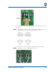
6. Thread the AC power cable downward through the first opening on the Cable
Strain Relief Bracket.
7. Wrap the excess cable around the Cable Strain Relief Bracket.
8. Remove approximately a ½” of insulation from the green ground wire to
expose the copper.
9. Insert the ground wire (from the right) into the bottom of the grounding termi-
nal.
10. Tighten the grounding terminal to secure the wire. for more information, see
“Securing the Cables” on page 31.
Grounding Instructions for AC HFC and UPS DC Power Options
Follow these grounding instructions:
1. Open the chassis door using a Phillips or flathead screwdriver to loosen the
panel fasteners.
2. Loosen the dome nut on the conduit/cable grips.
3. Remove the protective shields covering the AC and UPS terminal blocks.
4. Loosen the grounding terminal using a flathead screwdriver.
5. Insert the ground wire through conduit/cable grip #1.
6. Wrap the excess wire around the cable strain relief bracket.
7. Insert the ground wire (from the right) into the bottom of the grounding termi-
nal. (Verify that the copper is exposed if the wire is insulated).
8. Tighten the ground terminal to secure the wire. For more information, see
“Securing the Cables” on page 31.
Connect the Telephone Cables
The M-eMTA has two options for connecting telephone cables:
•RJ-21
• Punch down terminals
• Do not connect the RJ-21 and the punch down terminals; use
one option only.
• The maximum ring loading across all telephone lines in the
SBV5506 is 20REN. The maximum per blade is 5REN per
port and 10REN total.
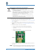
RJ-21 Cable
Follow these steps to connect the RJ-21 cable:
1. Insert the RJ-21 cable through the coupling #3.
2. Connect the RJ-21 cable to the RJ-21 connector on the backplane.
3. Tighten the cable using a screwdriver.
4. Secure the RJ-21 cable with a cable tie. For more information, see “Securing
the Cables” on page 31.
NOTE: