
Installation guide


16 M-eMTA Installation Guide
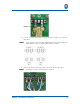
Punch-Down Terminal
Follow these steps to connect the punch down terminal:
1. Insert telephone cables through the #3 coupling.
2. Lift the first punch down terminal.
3. Insert the individual strands (Tip = green, Ring = red).
4. Return the punch down terminal to the down position.
5. Repeat steps 1–4 for additional phone lines.
6. Secure the telephone lines with a cable tie. For more information, see
“Securing the Cables” on page 31.
Connect the Data Cable(s)
Follow these steps to connect the data cable(s):
1. Insert the Ethernet (RJ-45) cable through the #3 coupling.
2. Connect the Ethernet cable to the Ethernet ports on the backplane.
3. Repeat steps 1 and 2 for additional lines.
4. Secure the cable using a cable tie. For more information, see “Securing the
Cables” on page 31.
The data ports can supply up to 3W maximum (18W total) to power an
external MoCA bridge device, Power Over Ethernet (POE).
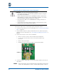
Connect the RF Cable
Follow these steps to connect the RF connector:
1. Measure the RF power level to ensure that it is between -5dBmV and
+10dBmV.
2. Insert the coaxial cable through the #2 coupling.
3. Route and connect the cable to the F–type connector on the backplane.
(Torque to 15–20 in-lbs.)
4. Secure the cable using a cable tie. For more information, see “Securing the
Cables” on page 31.
NOTE: