
Installation guide


18 M-eMTA Installation Guide
Connecting the AC Facility Power Source (Hardwire)
Connecting the Power and Jumper Cables (Indoor or Outdoor)
Follow these steps when connecting the power and jumper cables:
1. Connect the ground wire. For more information, see “Connect the Grounding
Wire” on page 14.
2. Ensure that the telephone, data, and the RF-Connector cables are properly
attached. For more information, see “Grounding and Cabling the Chassis” on
page 13.
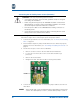
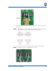
3. Follow these steps to remove the four bus-bars:
• Remove screws 1 and 3 on the AC1 and AC2 terminal blocks.
• Loosen (do not remove) the screws on the SP1 and SP2 surge
protectors.
• Remove the four bus bars.
• Retighten the SP1 and SP2 nuts after removing the bus-bars.
4. Connect the power cables and one end of the jumper cables to the AC1 ter-
minal block.
Place the flat side of the ring terminals back-to-back before inserting the
screws. Hot cables [black] = screw 1, neutral cables [white] = screw 3.
CAUTION: USE only one powering option at a time.
• To avoid personal injury, follow the NEC guidelines and/or local regula-
tions during the installation.
• When using the facility power, the SBV5506 should be connected to a
20-amp branch circuit that is part of the building installation. A licensed
electrician may be required to make this connection.
• Wire the power cables to the SBV5506 before making connection to
the facility power.
• To turn the unit on and off; the power cables connecting the unit to the
facility power acts as the disconnect device.
NOTE: