
Installation guide


Chapter 3: Hardware Installation 19
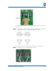
5. Connect the other end of each jumper cable to the AC2 terminal block.
Hot [black] = screw 1, neutral [white] = screw 3.
6. Secure the power cable using the strain relief bushing. For more information,
see “Securing the Cables” on page 31. Note that any cabling outside the inte-
rior of the premise should be contained inside a conduit.
7. Slide the AC power supply modules (left and right) into the power supply
enclosure area.
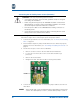
8. Insert the blade(s) into the chassis. For more information, see “Installing the
Blades” on page 29.
9. Reattach the protective shields over the AC1 and AC2 terminal blocks.
10. Place the chassis onto the wall mount bracket. For more information, see
“Mounting the Chassis Onto the Wall Bracket” on page 29.
11. Connect to facility power.
12. Verify that the unit is operational by observing the LED’s on the blades, check-
ing for a dial tone, and sending/receiving calls.
WARNING: You must put on an Electrostatic Discharge (ESD) wristband
before continuing.
NOTE: