
Installation guide


Chapter 3: Hardware Installation 25
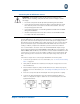
Connecting the UPS DC Power Source
Follow these steps to connect the UPS DC power source:
1. Connect the ground wire. For more information, see “Connect the Grounding
Wire” on page 14.
2. Verify that the bus bars are installed (connecting the surge protector to the
UPS terminal block).
3. Ensure that the telephone, data, and the RF-Connector cables are properly
attached. For more information, see “Grounding and Cabling the Chassis” on
page 13.
4. Measure the voltage from the UPS. Ensure that the voltage measures
between +10 VDC to +14 VDC and that the polarity of the wires is correct
(RED = +12 VDC and Black = 12 VDC return).
5. Turn off the 12 VDC UPS power.
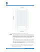
6. Insert the non-powered DC twisted pair wires through the #1 coupling.
7. Connect the DC twisted pair wires to SP3 (Red =1, Black = 2).
8. Connect the four discrete status lines if applicable [AC Fail (6), REPL BATT (7),
BATT MISS (8), BATT LOW (9) and UPS GND (10)].
CAUTION: Ensure that the UPS DC power source is not powered.
• To avoid personal injury, use the NEC guidelines during the installation.
• To turn the unit on and off; the power cables connecting the unit to the
UPS DC power source acts as the disconnect device.
• Do not use the power supply modules with this option.
• Use only one powering option at a time.
• Use an ESD wrist band during the installation.
WARNING: You must put on an Electrostatic Discharge (ESD) wristband
before continuing.