
Installation guide


26 M-eMTA Installation Guide
9. Insert the blade(s) into the chassis. For more information, see “Installing the
Blades” on page 29.
10. Reattach the protective shields over the terminal blocks.
11. Place the chassis onto the wall mount bracket. For more information, see
“Mounting the Chassis Onto the Wall Bracket” on page 29.
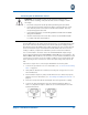
12. Connect the UPS to the power source to activate the UPS +12 VDC output.
13. Verify that the unit is operational by observing the LEDs on the blades, check-
ing for a dial tone, and making sure calls can be made using the telephone
lines.
14. Secure the power cables using the cable strain relief bracket. For more infor-
mation, see “Securing the Cables” on page 31.
Installing the Wall Bracket
The wall bracket and screws are shipped with the M-eMTA; they are located in
the foam pocket in the packaging.
Required Tools
The following tools are required for mounting the wall bracket:
•Drill
• Drill bit recommended for the mounting surface
(i.e., 1/8” twist drill bit for siding)
• 7/16” socket or box-end wrench
• Pencil or medium tip permanent marker
• Chalk (use a color visible on the mounting surface)
• Hammer (brick and concrete)
• Leveling tool
• Dust mask
• Safety glasses
• Anchors and screws (For more information, see the following table.)
CAUTION: Motorola recommends that installers mount the wall bracket
and then cable the M-eMTA before placing the chassis onto the bracket.
Wear safety glasses and a dust mask when performing this procedure.