
Installation guide


32 M-eMTA Installation Guide
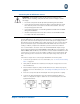
Space the cable ties approximately 2 inches from each other. Do not fully
tighten the bundle cable ties.
6. Feed the secured cable tie through the bundle cable ties and tighten.
7. Trim the excess material from the cable ties using wire cutter.
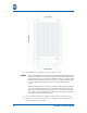
Securing the Chassis
After completing the installation, close the door, torque the panel fasteners to
20 in-lbs., and insert and close a lock in the padlock slot on the door.
Replacing the Fuses
Prior to replacing the F1, F2, and F3 fuses, make sure that all power sources have
been disconnected. Only replace with the following types of fuses:
• F1 and F2 – (2A/250V/IEC 60127-3/IV, T)
• F3 – (10A/250V/IEC 60127-3/IV, T)
The fuses are located on the SBV5506 backplane. All of the fuses are field
replaceable and can be removed and inserted into the fuse holders by pulling or
pushing on them. For more information, see “Backplane Components” on
page 4.
NOTE: