Symbol DS6707 Digital Imager Scanner Product Reference Guide
Symbol DS6707 Digital Imager Scanner Product Reference Guide 72E-83978-06 Revision A May 2009
ii Symbol DS6707 Digital Imager Scanner Product Reference Guide © 2007-2009 by Motorola, Inc. All rights reserved. No part of this publication may be reproduced or used in any form, or by any electrical or mechanical means, without permission in writing from Motorola. This includes electronic or mechanical means, such as photocopying, recording, or information storage and retrieval systems. The material in this manual is subject to change without notice.
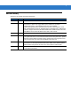
iii Revision History Changes to the original manual are listed below: Change Date Description -01 Rev A 8/2006 Initial Release.
iv Symbol DS6707 Digital Imager Scanner Product Reference Guide
Table of Contents About This Guide Introduction .................................................................................................................... Configurations................................................................................................................ Chapter Descriptions ..................................................................................................... Notational Conventions...........................................................................
vi Symbol DS6707 Digital Imager Scanner Product Reference Guide Symbol DS6707-DC Document Capture Digital Imager Scanner - 1D Bar Codes . Symbol DS6707-DC Document Capture Digital Imager Scanner - 2D Bar Codes . Symbol DS6707-DP Direct Part Mark Digital Imager Scanner - 1D and PDF417 Bar Codes ................................................................................................. Symbol DS6707-DP Direct Part Mark Digital Imager Scanner - 2D Bar Codes .....
Table of Contents Chapter 5: Imaging Preferences Introduction ................................................................................................................... Scanning Sequence Examples ..................................................................................... Errors While Scanning .................................................................................................. Imaging Preferences Parameter Defaults ............................................................
viii Symbol DS6707 Digital Imager Scanner Product Reference Guide Host Serial Response Time-out .............................................................................. Host Character Time-out ......................................................................................... Multipacket Option .................................................................................................. Interpacket Delay .....................................................................................
Table of Contents Chapter 9: 123Scan Introduction ................................................................................................................... 9-1 123Scan Parameter ...................................................................................................... 9-1 Chapter 10: Symbologies Introduction ................................................................................................................... Scanning Sequence Examples ....................................
x Symbol DS6707 Digital Imager Scanner Product Reference Guide Set Lengths for Code 11 ......................................................................................... Code 11 Check Digit Verification ............................................................................ Transmit Code 11 Check Digits .............................................................................. Interleaved 2 of 5 (ITF) .........................................................................................
Table of Contents Composite CC-A/B .................................................................................................. Composite TLC-39 .................................................................................................. UPC Composite Mode ............................................................................................ Composite Beep Mode ...........................................................................................
xii Symbol DS6707 Digital Imager Scanner Product Reference Guide Code Lengths .......................................................................................................... Message Containing A Specific Data String ........................................................... Actions .......................................................................................................................... Send Data ..................................................................................
Table of Contents Index Tell Us What You Think...
xiv Symbol DS6707 Digital Imager Scanner Product Reference Guide
About This Guide Introduction The Symbol DS6707 Digital Imager Scanner Product Reference Guide provides general instructions for setting up, operating, maintaining, and troubleshooting the Symbol DS6707 digital imager scanner. Configurations This guide includes the following digital imager scanner configurations: • Symbol DS6707-SR: Standard Range digital imager scanner for point of sale scanning. • Symbol DS6707-DC: Document Capture digital imager scanner for 8 1/2 in. by 11 in. imaging.
xvi Symbol DS6707 Digital Imager Scanner Product Reference Guide • Chapter 6, SSI Interface describes how to set up the digital imager scanner with a Simple Serial Interface (SSI) host. When using SSI, program the digital imager scanner via bar code menu or SSI host commands. • Chapter 7, USB Interface describes how to set up the digital imager scanner with a USB host.
About This Guide xvii • Throughout the programming bar code menus, asterisks (*) are used to denote default parameter settings. * Indicates Default *Baud Rate 9600 Feature/Option Related Documents The Symbol DS6707 Digital Imager Scanner Quick Start Guide, p/n 72-83972-xx, provides general information for getting started with the Symbol DS6707 digital imager scanner, and includes basic set up and operation instructions. For the latest version of this guide and all guides, go to: http://www.motorola.
Chapter 1 Getting Started Introduction The Symbol DS6707 digital imager scanner combines superior 1D and 2D omnidirectional bar code scanning and sub-second image capture and transfer to provide the best value in a digital imager scanner. Whether in hand-held mode or presentation (hands-free) mode in a stand, the digital imager scanner ensures comfort and ease of use for extended periods of time.
Getting Started 1-2 Supported Interfaces The Symbol DS6707digital imager scanner supports: • Simple Serial Interface (SSI) connection to a host. When using SSI, program the digital imager scanner via bar code menu or SSI host commands. • Standard RS-232 connection to a host. Scan bar code menus to set up communication between the digital imager scanner and the host. • USB connection to a host. The digital imager scanner autodetects a USB host and defaults to the HID keyboard interface type.
1-3 Symbol DS6707 Digital Imager Scanner Product Reference Guide Setting Up the Digital Imager Scanner Installing the Interface Cable 1. Plug the interface cable modular connector into the cable interface port on the bottom of the scanner handle. See Figure 1-2. 2. Gently tug the cable to ensure the connector is properly secured. 3. Connect the other end of the interface cable to the host (see the specific host chapter for information on host connections).
Getting Started 1-4 Connecting Power (if required) If the host does not provide power to the digital imager scanner, connect an external power supply: 1. Connect the interface cable to the bottom of the digital imager scanner, as described in Installing the Interface Cable on page 1-3. 2. Connect the other end of the interface cable to the host (refer to the host manual to locate the correct port). 3. Plug the power supply into the power jack on the interface cable.
1-5 Symbol DS6707 Digital Imager Scanner Product Reference Guide Wall Mount To use the optional wall mount to mount the digital imager scanner on a wall, place the mount in the desired location on the wall and secure by inserting two screws* appropriate for the mounting surface through the screw holes on the mount, and into the surface. Insert the digital imager scanner into the mount as shown. Figure 1-5 Securing the Wall Mount *The recommended screws are two #6 screws (1” long) and two #6 washers.
Chapter 2 Scanning Introduction This chapter provides beeper and LED definitions, techniques involved in scanning bar codes, general instructions and tips about scanning, and decode zone diagrams.
2-2 Symbol DS6707 Digital Imager Scanner Product Reference Guide Beeper Definitions The digital imager scanner issues different beep sequences and patterns to indicate status. Table 2-1 defines beep sequences that occur during both normal scanning and while programming the digital imager scanner. Table 2-1 Beeper Definitions Beeper Sequence Indication Standard Use Low/medium/high beeps Power up. Short high beep A bar code symbol was decoded (if decode beeper is enabled).
Scanning Table 2-1 Beeper Definitions (Continued) Beeper Sequence Indication Fast warble beep Aborting MPDF sequence. Low/high beeps Flushing an already empty MPDF buffer. ADF Programming: Normal Data Entry. Duration of tones are short. High/low beeps Enter another digit. Add leading zeros to the front if necessary. Low/low beeps Enter another alphabetic character or scan the End of Message bar code. High/high beeps Enter another criterion or action, or scan the Save Rule bar code.
2-4 Symbol DS6707 Digital Imager Scanner Product Reference Guide LED Definitions In addition to beep sequences, the digital imager scanner uses a two-color LED to indicate status. Table 2-2 defines LED colors that display during scanning. Table 2-2 Standard LED Definitions LED Indication Off No power is applied to the digital imager scanner, or the digital imager scanner is on and ready to scan. Green A bar code was successfully decoded.
Scanning 3. 2-5 When the digital imager scanner senses movement, in its default Auto Aim trigger mode, it projects a red laser aiming pattern (Figure 2-3) which allows positioning the bar code or object within the field of view. (To turn off the default Auto Aim trigger mode, see Trigger Mode on page 4-8.) If necessary, the digital imager scanner turns on its red LEDs to illuminate the target bar code. The DS6707-DP version uses a donut-shaped pattern with a center aiming dot.
2-6 Symbol DS6707 Digital Imager Scanner Product Reference Guide Aiming Hold the digital imager scanner between two and nine inches (depending on symbol density; see Decode Zones on page 2-8) from the symbol, centering the aiming pattern on the symbol. Ensure the cross hair falls on the symbol. For the DS6707-DP, ensure part of the symbol is visible within the donut-shaped pattern.
Scanning 2-7 Scanning in Presentation Mode The optional Intellistand adds greater flexibility to scanning operation. When you insert the digital imager scanner into the stand’s “cup,” the scanner’s built-in sensor places the scanner in presentation (hands-free) mode. When you remove the digital imager scanner from the stand it operates in its normal hand-held mode.
2-8 Symbol DS6707 Digital Imager Scanner Product Reference Guide Decode Zones Symbol DS6707-SR Standard Range Digital Imager Scanner - 1D Bar Codes Note: Typical performance at 73.4O F (23O C) on high quality symbols. DS6707-SR 5 mil (Code 39) 5.4 In . cm 10 3 1 .6 5 12.7 W i d t h 0 0 o f 5 12.7 0.9 10 mil I 2 of 5 1.0 7.9 10 25.4 F i e l d 13 mil (100% UPC/EAN) 8.4 0.9 20 mil (Code 39) 0.9 12.9 Postnet 2.6 In . 0 cm 0 5 12.7 10 25.4 12.5 15 38.
Scanning Symbol DS6707-SR Standard Range Digital Imager Scanner - 2D Bar Codes O O Note: Typical performance at 73.4 F (23 C) on high quality symbols. In . DS6707-SR cm 10 3 1 .6 5 12.7 W i d t h 0 0 o f 5 12.7 6.6 mil PDF417 5.2 1.4 10 10 mil QR Code 25.4 F i e l d 6.8 2.6 PDF417 (10 mil) 6.2 1.4 10 mil MicroPDF 2.3 7.50 Datamatrix (10 mil) 7.50 35 mil Maxicode 1.5 1.10 In . 0 cm 0 5 12.7 10 25.4 12.8 15 38.
2 - 10 Symbol DS6707 Digital Imager Scanner Product Reference Guide Symbol DS6707-DC Document Capture Digital Imager Scanner - 1D Bar Codes O O Note: Typical performance at 73.4 F (23 C) on high quality symbols. DS6707-DC In . 15 cm 38.1 10 25.4 5 12.7 W i d t h 0 0 o f 5 12.7 10 25.4 15 38.1 5 mil (Code 39) 8.4 2.6 2.6 1.7 0.9 Postnet 10 mil I 2 of 5 13.7 13 mil (100% UPC/EAN) 14.7 20 mil (Code 39) 1.2 In . 0 cm 0 12.5 F i e l d 21.4 5 12.7 10 25.4 15 38.1 20 50.
Scanning 2 - 11 Symbol DS6707-DC Document Capture Digital Imager Scanner - 2D Bar Codes O O Note: Typical performance at 73.4 F (23 C) on high quality symbols. In . 7.5 cm 19.1 5 12.7 2.5 6.4 W i d t h 0 0 o f 2.5 6.4 5 12.7 7.5 19.1 DS6707-DC 3.2 6.6 mil PDF417 10 mil QR Code 2.6 2.3 8.2 F i e l d 6.8 10 mil MicroPDF 7.5 PDF417 (10 mil) 11.1 2.4 Datamatrix (10 mil) 2.6 12.2 35 mil Maxicode 1.5 In . 0 cm 0 2.5 6.4 5 12.7 7.5 19.1 12.8 10 25.4 12.5 31.8 15 38.
2 - 12 Symbol DS6707 Digital Imager Scanner Product Reference Guide Symbol DS6707-DP Direct Part Mark Digital Imager Scanner - 1D and PDF417 Bar Codes O O Note: Typical performance at 73.4 F (23 C) on high quality symbols. DS6707-DP 3 mil Code 39 1.21 * 4 mil Code 39 1.83 * 5 mil Code 39 In . cm 2 5.1 1 2.5 W i d t h 0 0 o f 1 2.5 2 5.1 F i e l d 1.96 * 7.5 mil Code 39 * 10 mil Code 39 * 2.96 3.50 20 mil Code 39 * 13 mil 100% UPC * 6.21 3.59 6.67 mil PDF417 1.
Scanning 2 - 13 Symbol DS6707-DP Direct Part Mark Digital Imager Scanner - 2D Bar Codes O O Note: Typical performance at 73.4 F (23 C) on high quality symbols. DS6707-DP * * * 4 mil Data Matrix * * * In . 0 cm 0 1.71 10 mil Data Matrix 0.25 0.64 0 0 0.25 0.64 0.5 1.27 0.75 1.9 o f F i e l d 2.13 1.25 7.5 mil QR Code 1.67 10 mil QR Code 0.5 1.27 1.27 W i d t h 1.0 5 mil QR Code * 0.5 1.29 7.5 mil Data Matrix 4 mil QR Code cm 1.9 1.0 5 mil Data Matrix * In . 0.
2 - 14 Symbol DS6707 Digital Imager Scanner Product Reference Guide Symbol DS6707-HD High Density Digital Imager Scanner - 1D and PDF417 Bar Codes O Note: Typical performance at 73.4 F (23 C) on high quality symbols. O DS6707-HD 3 mil Code 39 2.42 0.84 0.42 0.29 4 mil Code 39 5 mil Code 39 3.38 7.5 mil Code 39 7.6 2 5.1 1 2.5 0 0 1 2.5 2 5.1 3 7.6 o f F i e l d 4.38 4.96 20 mil Code 39 0.42 13 mil 100% UPC/EAN 6.67 mil PDF417 0.63 10 mil PDF417 1.33 In .
Scanning 2 - 15 Symbol DS6707-HD High Density Digital Imager Scanner - 2D Bar Codes O Note: Typical performance at 73.4O F (23 C) on high quality symbols. In . cm 1.5 3.81 1.0 2.54 0.5 1.27 0 DS6707-HD 1.04 4 mil Data Matrix 1.13 4 mil QR Code 1 2.54 1.5 3.81 2.54 1.5 3.81 2.54 3.00 10 mil QR Code 0.46 1.0 F i e l d 3.50 7.5 mil QR Code 0.67 1.27 o f 2.17 5 mil QR Code 0.88 0.5 1.27 3.00 10 mil Data Matrix 0.54 0.5 2.50 7.5 mil Data Matrix 0.50 In . 0 cm 0 2.
2 - 16 Symbol DS6707 Digital Imager Scanner Product Reference Guide
Chapter 3 Maintenance & Technical Specifications Introduction This chapter provides suggested scanner maintenance, troubleshooting, technical specifications, and signal descriptions (pinouts). Maintenance Cleaning the scan window is the only maintenance required. A dirty window can affect scanning accuracy. • Do not allow abrasive material to touch the window. • Remove any dirt particles with a damp cloth. • Wipe the window using a tissue moistened with ammonia/water.
3-2 Symbol DS6707 Digital Imager Scanner Product Reference Guide Troubleshooting Table 3-1 Troubleshooting Problem The aiming pattern does not appear when pressing the trigger. Possible Causes Possible Solutions No power to the digital imager scanner. If the configuration requires a power supply, re-connect the power supply. Incorrect host interface cable is used. Connect the correct host interface cable. Interface/power cables are loose. Re-connect cables. Digital imager scanner is disabled.
Maintenance & Technical Specifications 3-3 Table 3-1 Troubleshooting (Continued) Problem Possible Causes Digital imager scanner decodes bar code, but does not transmit the data to the host. Digital imager scanner is not programmed for the correct host type. Scan the appropriate host type programming bar code. See the chapter corresponding to the host type. Interface cable is loose. Re-connect the cable. If 4 long low beeps are heard, a transmission error occurred.
3-4 Symbol DS6707 Digital Imager Scanner Product Reference Guide If after performing these checks the digital imager scanner still experiences problems, contact the distributor or contact Motorola Enterprise Mobility Support. See page xvii for the telephone numbers. NOTE Technical Specifications Table 3-2 Technical Specifications Item Description Physical Characteristics Dimensions Symbol DS6707-DP: All other models: 6.55 in. x 5.08 in. x 2.82 in. (16.6 cm x 12.9 cm x 7.1 cm) (H x L x W) 6.55 in.
Maintenance & Technical Specifications Table 3-2 Technical Specifications (Continued) Item Description Typical Working Distance: SR - Standard Range Focus 5 mil Code 39: 10 mil I 2 of 5: 13 mil 100% UPC/EAN: 20 mil Code 39: Postnet: 6.6 mil PDF417: 10 mil PDF417: 10 mil QR Code: 10 mil MicroPDF 10 mil Data Matrix: 35 mil Maxicode: 0.9 - 5.4 in. (2.3 - 13.7 cm) 1.0 - 7.9 in. (2.5 - 20.1 cm) 0.9 - 8.4 in. (2.3 - 21.3 cm) 0.9 - 12.9 in. (2.3 - 32.8 cm) 2.6 - 12.5 in. (6.6 - 31.8 cm) 3.4 - 5.7 in. (8.
3-6 Symbol DS6707 Digital Imager Scanner Product Reference Guide Table 3-2 Technical Specifications (Continued) Item Description Typical Working Distance: HD - High Density 3 mil Code 39: 4 mil Code 39: 5 mil Code 39: 7.5 mil Code 39: 10 mil Code 39: 20 mil Code 39: 13 mil 100% UPC: 6.67 mil PDF417: 10 mil PDF417: 15 mil PDF417: 4 mil Data Matrix: 5 mil Data Matrix: 7.5 mil Data Matrix: 10 mil Data Matrix: 4 mil QR Code: 5 mil QR Code: 7.5 mil QR Code: 10 mil QR Code: 0.84 - 2.42 in. (2.13 - 6.
Maintenance & Technical Specifications 3-7 Table 3-2 Technical Specifications (Continued) Item Description User Environment Operating Temperature 32º F to 104º F (0º C to 40º C) Storage Temperature -40º F to 158º F (-40º C to 70º C) Humidity 5% to 95%, non-condensing Drop Specifications Withstands multiple 5 ft. (1.52 m) drops to concrete at operating temperature extremes, and multiple 6 ft. (1.
3-8 Symbol DS6707 Digital Imager Scanner Product Reference Guide Digital Imager Scanner Signal Descriptions Bottom of digital imager scanner Cable interface port Pin 1 Pin 10 Interface cable modular connector Figure 3-1 Digital Imager Scanner Cable Pinouts The signal descriptions in Table 3-3 apply to the connectors on the Symbol DS6707 digital imager scanner and are for reference only.
Chapter 4 User Preferences & Miscellaneous Digital Imager Scanner Options Introduction You can program the digital imager scanner to perform various functions, or activate different features. This chapter describes each user preference feature and provides programming bar codes for selecting these features. The digital imager scanner ships with the settings shown in Table 4-1 on page 4-2 (also see Appendix A, Standard Default Parameters for all host device and miscellaneous defaults).
4-2 Symbol DS6707 Digital Imager Scanner Product Reference Guide Scanning Sequence Examples In most cases, scanning one bar code sets the parameter value. For example, to set the beeper tone to high, scan the High Frequency (beeper tone) bar code listed under Beeper Tone on page 4-5. The digital imager scanner issues a fast warble beep and the LED turns green, signifying a successful parameter entry.
User Preferences & Miscellaneous Digital Imager Scanner Options Table 4-1 User Preferences Parameter Defaults (Continued) Parameter Parameter Number Default Page Number Beep After Good Decode 38h Enable 4-11 Decoding Illumination F0h, 2Ah Enable 4-11 DP Illumination F1h, 3Bh Auto 4-12 Decode Aiming Pattern F0h, 32h Enable 4-13 Fuzzy 1D Processing F1h, 02h Enable 4-13 Decode Mirror Images F1h, 19h Never 4-14 Transmit Code ID Character 2Dh None 4-15 Prefix Value 63h, 69h 70
4-4 Symbol DS6707 Digital Imager Scanner Product Reference Guide User Preferences Set Default Parameter You can reset the Symbol DS6707 to two types of defaults: factory defaults or custom defaults. Scan the appropriate bar code below to reset the scanner to its default settings and/or set its current settings as custom defaults. • Restore Defaults - Scan this bar code to reset all default parameters as follows.
User Preferences & Miscellaneous Digital Imager Scanner Options 4-5 Parameter Scanning Parameter # ECh To disable decoding of parameter bar codes, including the Set Defaults parameter bar codes, scan the Disable Parameter Scanning bar code below. To re-enable decoding of parameter bar codes, scan Enable Parameter Scanning.
4-6 Symbol DS6707 Digital Imager Scanner Product Reference Guide Beeper Volume Parameter # 8Ch To select a beeper volume, scan the Low Volume, Medium Volume, or High Volume bar code. Low Volume (02h) Medium Volume (01h) *High Volume (00h) Power Mode Parameter # 80h This parameter determines whether or not power remains on after a decode attempt. In reduced power mode, the digital imager scanner enters into a low power consumption mode to preserve battery life after each decode attempt.
User Preferences & Miscellaneous Digital Imager Scanner Options 4-7 Time Delay to Low Power Mode Parameter # 92h NOTE This parameter only applies when Power Mode is set to Reduced Power. This parameter sets the time the digital imager scanner remains active after decoding. The digital imager scanner wakes upon trigger pull or when the host attempts to communicate with the digital imager scanner.
4-8 Symbol DS6707 Digital Imager Scanner Product Reference Guide Trigger Mode Parameter # 8Ah Select one of the following trigger modes for the digital imager scanner: • Level - A trigger pull activates decode processing. Decode processing continues until the bar code is decoded, the trigger is released, or the Decode Session Timeout is reached. • Blink - This trigger mode is used in presentation (hands-free) mode.
User Preferences & Miscellaneous Digital Imager Scanner Options 4-9 Picklist Mode Parameter # F0h 92h Picklist mode enables the digital imager scanner to decode only bar codes that are aligned under the laser crosshair. Select one of the following picklist modes for the digital imager scanner: • Disabled Always - Picklist mode is always disabled.
4 - 10 Symbol DS6707 Digital Imager Scanner Product Reference Guide Decode Session Timeout Parameter # 88h This parameter sets the maximum time decode processing continues during a scan attempt. It is programmable in 0.1 second increments from 0.5 to 9.9 seconds. The default timeout is 9.9 seconds. To set a Decode Session Timeout, scan the bar code below. Next, scan two numeric bar codes from Appendix D, Numeric Bar Codes that correspond to the desired on time.
User Preferences & Miscellaneous Digital Imager Scanner Options 4 - 11 Beep After Good Decode Parameter # 38h Select a bar code below to choose whether or not the digital scanner beeps after a good decode (or image capture in Snapshot mode). If you select Do Not Beep After Good Decode, the beeper still operates during parameter menu scanning and to indicate error conditions.
4 - 12 Symbol DS6707 Digital Imager Scanner Product Reference Guide DP Illumination Parameter # F1h, 3Bh This parameter controls whether the digital imager scanner uses direct or indirect illumination. Options are: • Auto Illumination: Alternates direct and indirect illumination. • Direct Illumination: Optimizes scanning of symbols printed on low contrast or opaque surfaces. For best results, hold the scanner at an angle when scanning using this option.
User Preferences & Miscellaneous Digital Imager Scanner Options 4 - 13 Decode Aiming Pattern Parameter # F0h, 32h This parameter only applies when in Decode Mode. Select Enable Decode Aiming Pattern to project the aiming pattern during bar code capture, or Disable Decode Aiming Pattern to turn the aiming pattern off. NOTE With picklist enabled, the decode aiming pattern flashes even when the Decode Aiming Pattern is disabled.
4 - 14 Symbol DS6707 Digital Imager Scanner Product Reference Guide Decode Mirror Images (Data Matrix Only) Parameter # F1h 19h Select an option for decoding mirror image Data Matrix bar codes: • Always - decode only Data Matrix bar codes that are mirror images • Never - do not decode Data Matrix bar codes that are mirror images • Auto - decode both mirrored and unmirrored Data Matrix bar codes.
User Preferences & Miscellaneous Digital Imager Scanner Options 4 - 15 Miscellaneous Scanner Parameters Transmit Code ID Character Parameter # 2Dh A Code ID character identifies the code type of a scanned bar code. This is useful when the digital imager scanner is decoding more than one code type. In addition to any single character prefix already selected, the Code ID character is inserted between the prefix and the decoded symbol.
4 - 16 Symbol DS6707 Digital Imager Scanner Product Reference Guide Prefix/Suffix Values Key Category Parameter # P = 63h, S1 = 62h, S2 = 64h Decimal Value Parameter # P = 69h, S1 = 68h, S2 = 6Ah You can append a prefix and/or one or two suffixes to scan data for use in data editing. To set a value for a prefix or suffix, scan a four-digit number (i.e., four bar codes from Appendix D, Numeric Bar Codes) that corresponds to that value. See Table E-1 on page E-1 for the four-digit codes.
User Preferences & Miscellaneous Digital Imager Scanner Options 4 - 17 Scan Data Transmission Format Parameter # EBh To change the scan data format, scan one of the following bar codes corresponding to the desired format. NOTE If using this parameter, do not use ADF rules to set the prefix/suffix. To set values for the prefix and/or suffix, see Prefix/Suffix Values on page 4-16.
4 - 18 Symbol DS6707 Digital Imager Scanner Product Reference Guide Scan Data Transmission Format (continued) (05h) (06h) (07h) FN1 Substitution Values Key Category Parameter # 67h Decimal Value Parameter # 6Dh The Wedge and USB HID Keyboard hosts support a FN1 Substitution feature. Enabling this substitutes any FN1 character (0x1b) in a GS1-128 bar code with a user-defined value.
User Preferences & Miscellaneous Digital Imager Scanner Options 4 - 19 Transmit “No Read” Message Parameter # 5Eh Scan a bar code below to select whether or not to transmit a No Read message. Enable this to transmit the characters NR when a bar code is not decoded. Disable this to send nothing to the host if a symbol does not decode.
4 - 20 Symbol DS6707 Digital Imager Scanner Product Reference Guide
Chapter 5 Imaging Preferences Introduction You can program the digital imager scanner to perform various functions, or activate different features. This chapter describes imaging preference features and provides programming bar codes for selecting these features. The digital imager scanner ships with the settings in Imaging Preferences Parameter Defaults on page 5-2 (also see Appendix A, Standard Default Parameters for all host device and miscellaneous defaults).
5-2 Symbol DS6707 Digital Imager Scanner Product Reference Guide Scanning Sequence Examples In most cases scanning one bar code sets the parameter value. For example, to disable the decode aiming pattern, scan the Disable Decode Aiming Pattern bar code under Decode Aiming Pattern on page 4-13. The digital imager scanner issues a fast warble beep and the LED turns green, signifying a successful parameter entry. Other parameters require scanning several bar codes.
Imaging Preferences Table 5-1 5-3 Imaging Preferences Parameter Defaults (Continued) Parameter Number Parameter Default Page Number Snapshot Aiming Pattern F0h 2Ch Enable 5-10 Image Cropping F0h 2Dh Disable 5-11 Crop to Pixel Addresses F4h F0h 3Bh; F4h F0h 3Ch; F4h F0h 3Dh; F4h F0h 3Eh 0 top, 0 left, 1023 bottom, 1279 right 5-12 Image Size (Number of Pixels) F0h 2Eh Full 5-13 Image Brightness (Target White) F0h 86h 180 5-14 JPEG Image Options F0h 2Bh Quality 5-14 JPEG Target F
5-4 Symbol DS6707 Digital Imager Scanner Product Reference Guide Imaging Preferences The parameters in this chapter control image capture characteristics. Image capture occurs in all modes of operation, including decode, video, and snapshot. Operational Modes The digital imager scanner has three modes of operation: • Decode Mode • Snapshot Mode • Video Mode.
Imaging Preferences 5-5 Low Light Enhancement Parameter # F1h, 64h In presentation mode, selecting Enable Low Light Enhancement causes illumination to remain on at a low level in low lighting conditions. Select Disable Low Light Enhancement to prevent illumination from remaining on under these conditions.
5-6 Symbol DS6707 Digital Imager Scanner Product Reference Guide Image Capture Autoexposure Parameter # F0h, 68h Select Enable Image Capture Autoexposure to allow the digital imager scanner to control gain settings and exposure (integration) time to best capture an image for the selected operation mode. Select Disable Image Capture Autoexposure to manually adjust the gain and exposure time (see the following pages).
Imaging Preferences Illumination Bank Control Parameter # F1h, 3Bh This parameter controls the illumination banks on the scan engine. Options are: • Full: Enables the full illumination system (default). • Auto: Switches the illumination system from left to right bank. • Left: Enables the left bank. • Right: Enables the right bank.
5-8 Symbol DS6707 Digital Imager Scanner Product Reference Guide Fixed Exposure Parameter #: F4h F1h 37h Type: Word Range: 5 - 5000 This parameter configures the exposure used in manual mode for both Decode and Snapshot/Video/Video viewfinder modes. Each integer value represents 100 μs worth of exposure. The default value is 100 which results in an exposure setting of 10 ms. To set the Fixed Exposure parameter, scan Fixed Exposure followed by four numeric bar codes representing the value.
Imaging Preferences 5-9 Gain/Exposure Priority for Snapshot Mode Parameter # F1h, 32h This parameter alters the digital imager scanner’s gain exposure priority when it acquires an image in Snapshot Mode in auto exposure mode. • Scan Low Exposure Priority to set a mode in which the digital imager scanner favors higher gain over exposure to capture an image. This results in an image that is less susceptible to motion blur at the expense of noise artifacts.
5 - 10 Symbol DS6707 Digital Imager Scanner Product Reference Guide Snapshot Mode Timeout Parameter # F0h, 43h This parameter sets the amount of time the digital imager scanner remains in Snapshot Mode. The digital imager scanner exits Snapshot Mode when you pull the trigger, or when the Snapshot Mode Timeout elapses. To set this timeout value, scan the bar code below followed by a bar code from Appendix D, Numeric Bar Codes. The default value is 0 which represents 30 seconds; values increment by 30.
Imaging Preferences 5 - 11 Image Cropping Parameter # F0h, 2Dh This parameter crops a captured image. Select Disable Image Cropping to present the full 1280 x 1024 pixels. Select Enable Image Cropping to crop the image to the pixel addresses set in Crop to Pixel Addresses on page 5-12. NOTE The digital scanner has a cropping resolution of 4 pixels. Setting the cropping area to less than 3 pixels transfers the entire image.
5 - 12 Symbol DS6707 Digital Imager Scanner Product Reference Guide Crop to Pixel Addresses Parameter # F4h, F0h, 3Bh (Top) Parameter # F4h, F0h, 3Ch (Left) Parameter # F4h, F0h, 3Dh (Bottom) Parameter # F4h, F0h, 3Eh (Right) If you selected Enable Image Cropping, set the pixel addresses from (0,0) to (1279,1023) to crop to. Columns are numbered from 0 to 1279, rows from 0 to 1023.
Imaging Preferences 5 - 13 Image Size (Number of Pixels) Parameter # F0h, 2Eh This option alters image resolution before compression. Multiple pixels are combined to one pixel, resulting in a smaller image containing the original content with reduced resolution.
5 - 14 Symbol DS6707 Digital Imager Scanner Product Reference Guide Image Brightness (Target White) Parameter # F0h 86h Type: Byte Range: 1 - 240 This parameter sets the Target White value used in Snapshot, Video and Video Viewfinder mode when using auto exposure. White and black are defined as 255 decimal and 0, respectively. Setting the value to the factory default of 180 sets the white level of the image to ~180.
Imaging Preferences 5 - 15 JPEG Target File Size Parameter # F4h, F1h, 31h Type: Word Range: 5-600 This parameter defines the target JPEG file size in terms 1 Kilobytes (1024 bytes). The default value is 160 kB which represents 160 Kilobytes. ! CAUTION JPEG compress may take 10 to 15 seconds based on the amount of information in the target image. Scanning JPEG Quality Selector (default setting) on page 5-14 produces a compressed image that is consistent in quality and compression time.
5 - 16 Symbol DS6707 Digital Imager Scanner Product Reference Guide Image Enhancement Parameter # F1h, 34h This parameter configures the digital imager scanner's Image Enhance feature. This feature uses a combination of edge sharpening and contrast enhancement to produce an image that is visually pleasing. The levels of image enhancement are: • Off (0) - Default • Low(1) • Med(2) • High(3).
Imaging Preferences 5 - 17 Image File Format Selector Parameter # F0h, 30h Select an image format appropriate for the system (BMP, TIFF, or JPEG). The digital imager scanner stores captured images in the selected format.
5 - 18 Symbol DS6707 Digital Imager Scanner Product Reference Guide Bits Per Pixel Parameter # F0h, 2Fh Select the number of significant bits per pixel (BPP) to use when capturing an image. Select 1 BPP for a black and white image, 4 BPP to assign 1 of 16 levels of grey to each pixel, or 8 BPP to assign 1 of 256 levels of grey to each pixel. NOTE The digital imager scanner ignores these settings for JPEG file formats, which only support 8 BPP.
Imaging Preferences 5 - 19 Signature Capture Parameter # 5Dh A signature capture bar code is a special-purpose symbology which delineates a signature capture area in a document with a machine-readable format. The recognition pattern is variable so it can optionally provide an index to various signatures. The region inside the bar code pattern is considered the signature capture area.
5 - 20 Symbol DS6707 Digital Imager Scanner Product Reference Guide Signature Capture File Format Selector Parameter # F0h, 39h Select a signature file format appropriate for the system (BMP, TIFF, or JPEG). The digital imager scanner stores captured signatures in the selected format.
Imaging Preferences 5 - 21 Signature Capture Bits Per Pixel Parameter # F0h, 3Ah Select the number of significant bits per pixel (BPP) to use when capturing a signature. Select 1 BPP for a black and white image, 4 BPP to assign 1 of 16 levels of grey to each pixel, or 8 BPP to assign 1 of 256 levels of grey to each pixel. NOTE The digital imager scanner ignores these settings for JPEG file formats, which only support 8 BPP.
5 - 22 Symbol DS6707 Digital Imager Scanner Product Reference Guide Signature Capture Width Parameter # F4h, F0h, 6Eh The aspect ratio of the Signature Capture Width and Signature Capture Height parameters must match that of the signature capture area. For example, a 4 x 1 inch signature capture area would require a 4 to 1 aspect ratio of width to height.
Imaging Preferences 5 - 23 Video View Finder Parameter # F0h, 44h Select Enable Video View Finder to project the video view finder while in Video Mode, or Disable Video View Finder to turn the video view finder off. *Disable Video View Finder (00h) Enable Video View Finder (01h) Target Video Frame Size Parameter # F0h, 48h Select the number of 100-byte blocks to transmit per second.
5 - 24 Symbol DS6707 Digital Imager Scanner Product Reference Guide Video View Finder Image Size Parameter # F0h, 49h Select the number of 100-byte blocks. Values range from 800 to 3000 bytes. Selecting a smaller value transmits more frames per second; selecting a larger value increases video quality. To set the Video View Finder Image Size, scan the bar code below followed by two bar codes from Appendix D, Numeric Bar Codes corresponding to the 100-byte value from 800 to 3000 bytes.
Chapter 6 SSI Interface Introduction This chapter describes how to set up the digital imager scanner with a Simple Serial Interface (SSI) host. When using SSI, program the digital imager scanner via bar code menu or SSI host commands. Throughout the programming bar code menus, default values are indicated with asterisks (*).
6-2 Symbol DS6707 Digital Imager Scanner Product Reference Guide Connecting Using Simple Serial Interface Connect the digital imager scanner to an SSI host. Interface Cable Serial Port Connector to Host Power Supply Cable Figure 6-1 SSI Host Connection 1. Attach the modular connector of the interface cable to the cable interface port on the digital imager scanner (see Installing the Interface Cable on page 1-3). 2. Connect the other end of the interface cable to the serial port on the host. 3.
SSI Interface 6-3 Simple Serial Interface Default Parameters Table 6-1 lists the defaults for the SSI host. There are two ways to change the default values: • Scan the appropriate bar codes in this guide. These new values replace the standard default values in memory. To recall the default parameter values, scan the Set Default Parameter on page 4-4. • Download data through the device’s serial port using SSI.
6-4 Symbol DS6707 Digital Imager Scanner Product Reference Guide SSI Host Parameters Baud Rate Parameter # 9Ch Baud rate is the number of bits of data transmitted per second. Set the digital imager scanner's baud rate to match the data rate setting of the host device. Otherwise, data may not reach the host or may reach it in distorted form. To enable the SSI host, scan the appropriate baud rate bar code that matches the baud rate setting of the host device.
SSI Interface Baud Rate (continued) Baud Rate 19,200 (07h) 38,400 (08h) 57,600 (0Ah) 115,200 (0Bh) 230,400 (0Ch) 6-5
6-6 Symbol DS6707 Digital Imager Scanner Product Reference Guide Parity Parameter # 9Eh A parity check bit is the most significant bit of each ASCII coded character. Select the parity type according to host device requirements. • Select Odd parity to set the parity bit to a value 0 or 1, based on data, to ensure that the coded character contains an odd number of 1 bits.
SSI Interface 6-7 Check Parity Parameter # 97h Select whether or not to check the parity of received characters. Use the Parity parameter to select the type of parity. *Check Parity (01h) Do Not Check Parity (00h) Software Handshaking Parameter # 9Fh This parameter offers control of the data transmission process in addition to that offered by hardware handshaking. Hardware handshaking is always enabled and cannot be disabled by the user.
6-8 Symbol DS6707 Digital Imager Scanner Product Reference Guide Host RTS Line State Parameter # 9Ah This parameter sets the expected idle state of the Serial Host RTS line. The SSI Interface is used with host applications which also implement the SSI protocol. However, you can also use the digital imager scanner in a "scan-and-transmit" mode to communicate with any standard serial communication software on a host PC (see Decode Data Packet Format on page 6-8).
SSI Interface 6-9 Stop Bit Select Parameter # 9Dh The stop bit(s) at the end of each transmitted character marks the end of transmission of one character and prepares the receiving (host) device for the next character in the serial data stream. Set the number of stop bits (one or two) to match host device requirements.
6 - 10 Symbol DS6707 Digital Imager Scanner Product Reference Guide Host Serial Response Time-out Parameter # 9Bh This parameter specifies how long the decoder waits for an ACK or NAK before resending. Also, if the decoder wants to send, and the host was already granted permission to send, the decoder waits for the designated time-out before declaring an error. To set the delay period (options are 2, 5, 7.5, or 9.9 seconds), scan one of the following bar codes.
SSI Interface 6 - 11 Host Character Time-out Parameter # EFh This parameter determines the maximum time the decoder waits between characters transmitted by the host before discarding the received data and declaring an error. To set the delay period (options are 200, 500, 750, or 990 ms), scan one of the following bar codes. NOTE Other values are available via SSI command.
6 - 12 Symbol DS6707 Digital Imager Scanner Product Reference Guide Multipacket Option Parameter # F0h, 4Eh This parameter controls ACK/NAK handshaking for multi-packet transmissions. • Multi-Packet Option 1: The host sends an ACK / NAK for each data packet during a multi-packet transmission. • Multi-Packet Option 2: The digital imager scanner sends data packets continuously, with no ACK/NAK handshaking to pace the transmission.
SSI Interface 6 - 13 Interpacket Delay Parameter # F0h, 4Fh This parameter specifies the interpacket delay when Multipacket Option 3 is selected. To set the delay period (options are 0, 25, 50, 75, or 99 ms), scan one of the following bar codes. NOTE Other values are available via SSI command.
6 - 14 Symbol DS6707 Digital Imager Scanner Product Reference Guide Event Reporting The host can request the digital imager scanner to provide certain information (events) relative to the digital imager scanner’s behavior. Enable or disable the events listed in Table 6-2 and on the following pages by scanning the appropriate bar codes.
SSI Interface 6 - 15 Boot Up Event Parameter # F0h, 02h When enabled, the digital imager scanner generates a message to the host when power is applied. When disabled, no notification is sent. Enable Boot Up Event (01h) *Disable Boot Up Event (00h) Parameter Event Parameter # F0h, 03h When enabled, the digital imager scanner generates a message to the host when one of the events specified in Table 6-2 on page 6-14 occurs. When disabled, no notification is sent.
6 - 16 Symbol DS6707 Digital Imager Scanner Product Reference Guide
Chapter 7 USB Interface Introduction This chapter describes how to set up the digital imager scanner with a USB host. The digital imager scanner connects directly to a USB host, or a powered USB hub, which powers it. No additional power supply is required. Throughout the programming bar code menus, asterisks (*) indicate default values. *Indicates Default NOTE *North American Standard USB Keyboard Feature/Option Most computer monitors allow scanning the bar codes directly on the screen.
7-2 Symbol DS6707 Digital Imager Scanner Product Reference Guide Connecting a USB Interface Interface Cable USB Series A Connector Figure 7-1 USB Connection The digital imager scanner connects with USB-capable hosts including: • Desktop PCs and notebooks • Apple™ iMac, G4, iBooks (North America only) • IBM SurePOS terminals • Sun, IBM, and other network computers that support more than one keyboard.
USB Interface USB Parameter Defaults Table 7-1 lists the defaults for USB host parameters. To change an option, scan the appropriate bar code(s) provided in the Parameter Descriptions section beginning on page 7-4. NOTE See Appendix A, Standard Default Parameters for all user preferences, hosts, symbologies, and miscellaneous default parameters.
7-4 Symbol DS6707 Digital Imager Scanner Product Reference Guide USB Host Parameters USB Device Type Select the desired USB device type. NOTE When changing USB Device Types, the digital imager scanner automatically resets and issues the standard startup beep sequences.
USB Interface 7-5 USB Device Type (continued) Symbol Native API (SNAPI) with Imaging Interface Symbol Native API (SNAPI) without Imaging Interface Symbol Native API (SNAPI) Status Handshaking After selecting a SNAPI interface as the USB device type, select whether to enable or disable status handshaking.
7-6 Symbol DS6707 Digital Imager Scanner Product Reference Guide USB Country Keyboard Types (Country Codes) Scan the bar code corresponding to the keyboard type. This setting applies only to the USB HID Keyboard Emulation device. NOTE When changing USB country keyboard types the digital imager scanner automatically resets and issues the standard startup beep sequences.
USB Interface USB Country Keyboard Types (continued) Spanish Windows Italian Windows Swedish Windows UK English Windows Japanese Windows (ASCII) Portuguese-Brazilian Windows 7-7
7-8 Symbol DS6707 Digital Imager Scanner Product Reference Guide USB Keystroke Delay This parameter sets the delay, in milliseconds, between emulated keystrokes. Scan a bar code below to increase the delay when hosts require slower data transmission. *No Delay Medium Delay (20 msec) Long Delay (40 msec) USB CAPS Lock Override This option applies only to the HID Keyboard Emulation device. Enable this to preserve the case of the data regardless of the state of the Caps Lock key.
USB Interface 7-9 USB Ignore Unknown Characters This option applies only to the HID Keyboard Emulation device and IBM device. Unknown characters are characters the host does not recognize. Select Send Bar Codes With Unknown Characters to send all bar code data except for unknown characters. The scanner sounds no error beeps.
7 - 10 Symbol DS6707 Digital Imager Scanner Product Reference Guide Emulate Keypad with Leading Zero Enable this to send character sequences sent over the numeric keypad as ISO characters which have a leading zero. For example ASCII A transmits as “ALT MAKE” 0 0 6 5 “ALT BREAK”. *Disable Keypad Emulation with Leading Zero Enable Keypad Emulation with Leading Zero USB Keyboard FN 1 Substitution This option applies only to the USB HID Keyboard Emulation device.
USB Interface 7 - 11 Function Key Mapping ASCII values under 32 are normally sent as a control-key sequences (see Table 7-2 on page 7-13). Enable this to send the keys in bold in place of the standard key mapping. Table entries that do not have a bold entry remain the same whether or not you enable this parameter.
7 - 12 Symbol DS6707 Digital Imager Scanner Product Reference Guide Convert Case Enable this to convert all bar code data to the selected case.
USB Interface 7 - 13 ASCII Character Set for USB Table 7-2 USB Prefix/Suffix Values Prefix/ Suffix Value Full ASCII Code 39 Encode Char.
7 - 14 Symbol DS6707 Digital Imager Scanner Product Reference Guide Table 7-2 USB Prefix/Suffix Values (Continued) Prefix/ Suffix Value Full ASCII Code 39 Encode Char.
USB Interface 7 - 15 Table 7-2 USB Prefix/Suffix Values (Continued) Prefix/ Suffix Value Full ASCII Code 39 Encode Char.
7 - 16 Symbol DS6707 Digital Imager Scanner Product Reference Guide Table 7-2 USB Prefix/Suffix Values (Continued) Prefix/ Suffix Value Full ASCII Code 39 Encode Char.
USB Interface 7 - 17 Table 7-2 USB Prefix/Suffix Values (Continued) Prefix/ Suffix Value Full ASCII Code 39 Encode Char.acter Keystroke 1109 +M m 1110 +N n 1111 +O o 1112 +P p 1113 +Q q 1114 +R r 1115 +S s 1116 +T t 1117 +U u 1118 +V v 1119 +W w 1120 +X x 1121 +Y y 1122 +Z z 1123 %P { 1124 %Q | 1125 %R } 1126 %S ~ 1 The keystroke in bold transmits only if you enabled Function Key Mapping on page 7-11. Otherwise, the unbolded keystroke transmits.
7 - 18 Symbol DS6707 Digital Imager Scanner Product Reference Guide Table 7-3 USB ALT Key Character Set (Continued) ALT Keys Keystroke 2072 ALT H 2073 ALT I 2074 ALT J 2075 ALT K 2076 ALT L 2077 ALT M 2078 ALT N 2079 ALT O 2080 ALT P 2081 ALT Q 2082 ALT R 2083 ALT S 2084 ALT T 2085 ALT U 2086 ALT V 2087 ALT W 2088 ALT X 2089 ALT Y 2090 ALT Z Table 7-4 USB GUI Key Character Set GUI Key Keystroke 3000 Right Control Key 3048 GUI 0 3049 GUI 1 3050 GUI 2 3051
USB Interface 7 - 19 Table 7-4 USB GUI Key Character Set (Continued) GUI Key Keystroke 3054 GUI 6 3055 GUI 7 3056 GUI 8 3057 GUI 9 3065 GUI A 3066 GUI B 3067 GUI C 3068 GUI D 3069 GUI E 3070 GUI F 3071 GUI G 3072 GUI H 3073 GUI I 3074 GUI J 3075 GUI K 3076 GUI L 3077 GUI M 3078 GUI N 3079 GUI O 3080 GUI P 3081 GUI Q 3082 GUI R 3083 GUI S 3084 GUI T 3085 GUI U 3086 GUI V 3087 GUI W Note: GUI Shift Keys - The Apple™ iMac keyboard has an apple key on ei
7 - 20 Symbol DS6707 Digital Imager Scanner Product Reference Guide Table 7-4 USB GUI Key Character Set (Continued) GUI Key Keystroke 3088 GUI X 3089 GUI Y 3090 GUI Z Note: GUI Shift Keys - The Apple™ iMac keyboard has an apple key on either side of the space bar. Windows-based systems have a GUI key to the left of the left ALT key, and to the right of the right ALT key.
USB Interface 7 - 21 Table 7-5 USB F Key Character Set (Continued) F Keys Keystroke 5022 F22 5023 F23 5024 F24 Table 7-6 USB Numeric Keypad Character Set Numeric Keypad Keystroke 6042 * 6043 + 6044 undefined 6045 - 6046 .
7 - 22 Symbol DS6707 Digital Imager Scanner Product Reference Guide Table 7-7 USB Extended Keypad Character Set (Continued) Extended Keypad Keystroke 7006 Pause 7007 Scroll Lock 7008 Backspace 7009 Tab 7010 Print Screen 7011 Insert 7012 Home 7013 Enter 7014 Escape 7015 Up Arrow 7016 Down Arrow 7017 Left Arrow 7018 Right Arrow
Chapter 8 RS-232 Interface Introduction This chapter describes how to set up the digital imager scanner with an RS-232 host. Use the RS-232 interface to connect the digital imager scanner to point-of-sale devices, host computers, or other devices with an available RS-232 port (e.g., com port). If your host does not appear in Table 8-2, refer to the documentation for the host device to set communication parameters to match the host.
8-2 Symbol DS6707 Digital Imager Scanner Product Reference Guide Connecting an RS-232 Interface The digital imager scanner connects directly to the host computer. Interface Cable Serial Port Connector to Host Power Supply Cable Figure 8-1 RS-232 Direct Connection NOTE Interface cables vary depending on configuration. The connectors illustrated in Figure 8-1 are examples only. The connectors may be different than those illustrated, but the steps to connect the scanner are the same. 1.
RS-232 Interface 8-3 RS-232 Parameter Defaults Table 8-1 lists the defaults for RS-232 host parameters. To change any option, scan the appropriate bar code(s) provided in the RS-232 Host Parameters section beginning on page 8-4. NOTE See Appendix A, Standard Default Parameters for all user preferences, hosts, symbologies, and miscellaneous default parameters.
8-4 Symbol DS6707 Digital Imager Scanner Product Reference Guide RS-232 Host Parameters Various RS-232 hosts use their own parameter default settings. Selecting standard, ICL, Fujitsu, Wincor-Nixdorf Mode A, Wincor-Nixdorf Mode B, OPOS/JPOS, Olivetti, or Omron sets the defaults listed in Table 8-2.
RS-232 Interface 8-5 RS-232 Host Parameters (continued) Selecting ICL, Fujitsu, Wincor-Nixdorf Mode A, Wincor-Nixdorf Mode B, OPOS/JPOS, Olivetti, or Omron enables the transmission of code ID characters listed in Table 8-3. These code ID characters are not programmable and are separate from the Transmit Code ID feature. Do not enable the Transmit Code ID feature for these terminals.
8-6 Symbol DS6707 Digital Imager Scanner Product Reference Guide RS-232 Host Types To select an RS-232 host interface, scan one of the following bar codes. Standard RS-2321 ICL RS-232 Wincor-Nixdorf RS-232 Mode A Wincor-Nixdorf RS-232 Mode B Olivetti ORS4500 Omron 1Scanning Enable RS-232 (No Variant) activates the RS-232 driver, but does not change port settings (e.g., parity, data bits, handshaking). Selecting another RS-232 host type bar code changes these settings.
RS-232 Interface 8-7 RS-232 Host Types (continued) OPOS/JPOS Fujitsu RS-232 Baud Rate Baud rate is the number of bits of data transmitted per second. Set the digital imager scanner's baud rate to match the baud rate setting of the host device. Otherwise, data may not reach the host device or may reach it in distorted form.
8-8 Symbol DS6707 Digital Imager Scanner Product Reference Guide Baud Rate (continued) *Baud Rate 9600 Baud Rate 19,200 Baud Rate 38,400 Baud Rate 57,600 Baud Rate 115,200
RS-232 Interface 8-9 Parity A parity check bit is the most significant bit of each ASCII coded character. Select the parity type according to host device requirements. • Select Odd parity to set the parity bit value to 0 or 1, based on data, to ensure that the coded character contains an odd number of 1 bits • Select Even parity to set the parity bit value to 0 or 1, based on data, to ensure that the coded character contains an even number of 1 bits. • Select None when no parity bit is required.
8 - 10 Symbol DS6707 Digital Imager Scanner Product Reference Guide Stop Bit Select The stop bit(s) at the end of each transmitted character marks the end of transmission of one character and prepares the receiving device for the next character in the serial data stream. Select the number of stop bits (one or two) based on the number the receiving terminal is programmed to accommodate. Set the number of stop bits to match host device requirements.
RS-232 Interface 8 - 11 Check Receive Errors Select whether or not to check the parity, framing, and overrun of received characters. The parity value of received characters is verified against the parity parameter selected above. *Check For Received Errors Do Not Check For Received Errors Hardware Handshaking The data interface consists of an RS-232 port designed to operate either with or without the hardware handshaking lines, Request to Send (RTS), and Clear to Send (CTS).
8 - 12 Symbol DS6707 Digital Imager Scanner Product Reference Guide Hardware Handshaking (continued) • None: Scan this bar code to disable hardware handshaking. • Standard RTS/CTS: Scan this bar code to select Standard RTS/CTS Hardware Handshaking. • RTS/CTS Option 1: If you select RTS/CTS Option 1, the digital imager scanner asserts RTS before transmitting and ignores the state of CTS. The digital imager scanner de-asserts RTS when the transmission is complete.
RS-232 Interface 8 - 13 Hardware Handshaking (continued) RTS/CTS Option 2 RTS/CTS Option 3 Software Handshaking This parameter offers control of the data transmission process in addition to, or instead of, that offered by hardware handshaking. There are five options. If software handshaking and hardware handshaking are both enabled, hardware handshaking takes precedence. • None: Select this option to transmit data immediately. No response is expected from host.
8 - 14 Symbol DS6707 Digital Imager Scanner Product Reference Guide Software Handshaking (continued) • XON/XOFF: An XOFF character turns the digital imager scanner transmission off until the digital imager scanner receives an XON character. There are two situations for XON/XOFF: • The scanner receives an XOFF before it has data to send. When the digital imager scanner has data to send, it waits up to Host Serial Response Time-out for an XON character before transmission.
RS-232 Interface 8 - 15 Host Serial Response Time-out This parameter specifies how long the digital imager scanner waits for an ACK, NAK, or CTS before determining that a transmission error occurred. This only applies when in one of the ACK/NAK software handshaking modes, or RTS/CTS hardware handshaking mode. *Minimum: 2 Sec Low: 2.5 Sec Medium: 5 Sec High: 7.5 Sec Maximum: 9.
8 - 16 Symbol DS6707 Digital Imager Scanner Product Reference Guide RTS Line State This parameter sets the idle state of the Serial Host RTS line. Scan a bar code below to select Low RTS or High RTS line state. *Host: Low RTS Host: High RTS Beep on If you enable this parameter, the digital imager scanner issues a beep when it detects a character on the RS-232 serial line. gains a user's attention to an illegal entry or other important event.
RS-232 Interface 8 - 17 Intercharacter Delay This parameter specifies the intercharacter delay inserted between character transmissions.
8 - 18 Symbol DS6707 Digital Imager Scanner Product Reference Guide Nixdorf Beep/LED Options If you selected Nixdorf Mode B, this indicates when the digital imager scanner beeps and turns on its LED after a decode. *Normal Operation (Beep/LED immediately after decode) Beep/LED After Transmission Beep/LED After CTS Pulse Ignore Unknown Characters Unknown characters are characters the host does not recognize.
RS-232 Interface 8 - 19 ASCII Character Set for RS-232 You can assign the values in Table 8-4 as prefixes or suffixes for ASCII character data transmission.
8 - 20 Symbol DS6707 Digital Imager Scanner Product Reference Guide Table 8-4 Prefix/Suffix Values (Continued) Prefix/Suffix Value Full ASCII Code 39 Encode Character ASCII Character 1027 %A ESC 1028 %B FS 1029 %C GS 1030 %D RS 1031 %E US 1032 Space Space 1033 /A ! 1034 /B " 1035 /C # 1036 /D $ 1037 /E % 1038 /F & 1039 /G ‘ 1040 /H ( 1041 /I ) 1042 /J * 1043 /K + 1044 /L , 1045 - - 1046 . .
RS-232 Interface 8 - 21 Table 8-4 Prefix/Suffix Values (Continued) Prefix/Suffix Value Full ASCII Code 39 Encode Character ASCII Character 1057 9 9 1058 /Z : 1059 %F ; 1060 %G < 1061 %H = 1062 %I > 1063 %J ? 1064 %V @ 1065 A A 1066 B B 1067 C C 1068 D D 1069 E E 1070 F F 1071 G G 1072 H H 1073 I I 1074 J J 1075 K K 1076 L L 1077 M M 1078 N N 1079 O O 1080 P P 1081 Q Q 1082 R R 1083 S S 1084 T T 1085 U U 1086 V V
8 - 22 Symbol DS6707 Digital Imager Scanner Product Reference Guide Table 8-4 Prefix/Suffix Values (Continued) Prefix/Suffix Value Full ASCII Code 39 Encode Character ASCII Character 1087 W W 1088 X X 1089 Y Y 1090 Z Z 1091 %K [ 1092 %L \ 1093 %M ] 1094 %N ^ 1095 %O _ 1096 %W ` 1097 +A a 1098 +B b 1099 +C c 1100 +D d 1101 +E e 1102 +F f 1103 +G g 1104 +H h 1105 +I i 1106 +J j 1107 +K k 1108 +L l 1109 +M m 1110 +N n 1111 +O o 111
RS-232 Interface 8 - 23 Table 8-4 Prefix/Suffix Values (Continued) Prefix/Suffix Value Full ASCII Code 39 Encode Character ASCII Character 1117 +U u 1118 +V v 1119 +W w 1120 +X x 1121 +Y y 1122 +Z z 1123 %P { 1124 %Q | 1125 %R } 1126 %S ~ 1127 Undefined 7013 ENTER
8 - 24 Symbol DS6707 Digital Imager Scanner Product Reference Guide
Chapter 9 123Scan Introduction 123Scan is a Windows®-based utility that programs the digital imager scanner with all parameters including Advanced Data Formatting (ADF) rules. An ADF rule modifies bar code data before sending it to the host to ensure compatibility between bar coded data and the host application. Program digital imager scanners via PC download or by scanning a sheet of bar codes generated by the 123Scan utility.
9-2 Symbol DS6707 Digital Imager Scanner Product Reference Guide
Chapter 10 Symbologies Introduction This chapter describes symbology features and provides programming bar codes for selecting these features. Before programming, follow the instructions in Chapter 1, Getting Started. To set feature values, scan a single bar code or a short bar code sequence. The settings are stored in non-volatile memory and are preserved even when you power down the digital imager scanner. NOTE Most computer monitors allow scanning the bar codes directly on the screen.
10 - 2 Symbol DS6707 Digital Imager Scanner Product Reference Guide Errors While Scanning Unless otherwise specified, to correct an error during a scanning sequence, just re-scan the correct parameter. Symbology Parameter Defaults Table 10-1 lists the defaults for all symbologies parameters. There are two ways to change the default values: • Scan the appropriate bar codes in this guide. These new values replace the standard default values in memory.
Symbologies 10 - 3 Table 10-1 Parameter Defaults (Continued) Parameter Parameter Number Default Page Number UPC-E1 Preamble 24h System Character 10-18 Convert UPC-E to A 25h Disable 10-19 Convert UPC-E1 to A 26h Disable 10-19 EAN-8/JAN-8 Extend 27h Disable 10-20 Bookland ISBN Format F1h 40h ISBN-10 10-21 UCC Coupon Extended Code 55h Disable 10-22 ISSN EAN F1h 69h Disable 10-22 Code 128 08h Enable 10-23 Set Length(s) for Code 128 D1h D2h Any Length 10-23 GS1-128 (for
10 - 4 Symbol DS6707 Digital Imager Scanner Product Reference Guide Table 10-1 Parameter Defaults (Continued) Parameter Parameter Number Default Page Number Code 11 Code 11 0Ah Disable 10-38 Set Lengths for Code 11 1Ch 1Dh 4 to 55 10-38 Code 11 Check Digit Verification 34h Disable 10-40 Transmit Code 11 Check Digit(s) 2Fh Disable 10-41 Interleaved 2 of 5 (ITF) 06h Enable 10-42 Set Lengths for I 2 of 5 16h 17h 14 10-42 I 2 of 5 Check Digit Verification 31h Disable 10-44 Tran
Symbologies 10 - 5 Table 10-1 Parameter Defaults (Continued) Parameter Parameter Number Default Page Number Matrix 2 of 5 Matrix 2 of 5 F1h 6Ah Disable 10-55 Matrix 2 of 5 Lengths F1h 6Bh F1h 6Ch 1 Length - 14 10-56 Matrix 2 of 5 Redundancy F1h 6Dh Disable 10-57 Matrix 2 of 5 Check Digit F1h 6Eh Disable 10-57 Transmit Matrix 2 of 5 Check Digit F1h 6Fh Disable 10-58 Inverse 1D F1h 4Ah SR, DC: Regular DP, HD: Autodetect 10-59 US Postnet 59h Enable 10-60 US Planet 5Ah Enable
10 - 6 Symbol DS6707 Digital Imager Scanner Product Reference Guide Table 10-1 Parameter Defaults (Continued) Parameter Parameter Number Default Page Number Composite Beep Mode F0h 8Eh Beep As Each Code Type is Decoded 10-70 GS1-128 Emulation Mode for UCC/EAN Composite Codes F0h ABh Disable 10-70 PDF417 0Fh Enable 10-71 MicroPDF417 E3h Disable 10-71 Code 128 Emulation 7Bh Disable 10-72 Data Matrix F0h 24h Enable 10-73 Data Matrix Inverse F1h 4Ch SR, DC: Regular DP, HD: Autode
Symbologies 10 - 7 UPC/EAN Enable/Disable UPC-A Parameter # 01h To enable or disable UPC-A, scan the appropriate bar code below. *Enable UPC-A (01h) Disable UPC-A (00h) Enable/Disable UPC-E Parameter # 02h To enable or disable UPC-E, scan the appropriate bar code below.
10 - 8 Symbol DS6707 Digital Imager Scanner Product Reference Guide Enable/Disable UPC-E1 Parameter # 0Ch UPC-E1 is disabled by default. To enable or disable UPC-E1, scan the appropriate bar code below. NOTE UPC-E1 is not a UCC (Uniform Code Council) approved symbology. Enable UPC-E1 (01h) *Disable UPC-E1 (00h) Enable/Disable EAN-8/JAN-8 Parameter # 04h To enable or disable EAN-8/JAN-8, scan the appropriate bar code below.
Symbologies 10 - 9 Enable/Disable EAN-13/JAN-13 Parameter # 03h To enable or disable EAN-13/JAN-13, scan the appropriate bar code below. *Enable EAN-13/JAN-13 (01h) Disable EAN-13/JAN-13 (00h) Enable/Disable Bookland EAN Parameter # 53h To enable or disable Bookland EAN, scan the appropriate bar code below. Enable Bookland EAN (01h) *Disable Bookland EAN (00h) NOTE If you enable Bookland EAN, select a Bookland ISBN Format on page 10-21.
10 - 10 Symbol DS6707 Digital Imager Scanner Product Reference Guide Decode UPC/EAN/JAN Supplementals Parameter # 10h Supplementals are bar codes appended according to specific format conventions (e.g., UPC A+2, UPC E+2, EAN 13+2). The following options are available: • If you select Ignore UPC/EAN with Supplementals, and the scanner is presented with a UPC/EAN plus supplemental symbol, the scanner decodes UPC/EAN and ignores the supplemental characters.
Symbologies 10 - 11 Decode UPC/EAN/JAN Supplementals (continued) Decode UPC/EAN/JAN Only With Supplementals (01h) *Ignore Supplementals (00h) Autodiscriminate UPC/EAN/JAN Supplementals (02h) Enable 378/379 Supplemental Mode (04h) Enable 978/979 Supplemental Mode (05h) Enable 977 Supplemental Mode (07h)
10 - 12 Symbol DS6707 Digital Imager Scanner Product Reference Guide Decode UPC/EAN/JAN Supplementals (continued) Enable 414/419/434/439 Supplemental Mode (06h) Enable 491 Supplemental Mode (08h) Enable Smart Supplemental Mode (03h) Supplemental User-Programmable Type 1 (09h) Supplemental User-Programmable Type 1 and 2 (0Ah) Smart Supplemental Plus User-Programmable 1 (0Bh) Smart Supplemental Plus User-Programmable 1 and 2 (0Ch)
Symbologies 10 - 13 User-Programmable Supplementals Supplemental 1: Parameter # F1h 43h Supplemental 2: Parameter # F1h 44h If you selected a Supplemental User-Programmable option from Decode UPC/EAN/JAN Supplementals on page 10-10, select User-Programmable Supplemental 1 to set the 3-digit prefix. Then select the 3 digits using the numeric bar codes beginning on page D-1. Select User-Programmable Supplemental 2 to set a second 3-digit prefix.
10 - 14 Symbol DS6707 Digital Imager Scanner Product Reference Guide UPC/EAN/JAN Supplemental Redundancy Parameter # 50h If you selected Autodiscriminate UPC/EAN/JAN Supplementals, this option adjusts the number of times a symbol without supplementals is decoded before transmission. The range is from two to thirty times. Five or above is recommended when decoding a mix of UPC/EAN/JAN symbols with and without supplementals. The default is set at 10. Scan the bar code below to set a decode redundancy value.
Symbologies 10 - 15 Transmit UPC-E Check Digit Parameter # 29h The check digit is the last character of the symbol used to verify the integrity of the data. Scan the appropriate bar code below to transmit the bar code data with or without the UPC-E check digit. It is always verified to guarantee the integrity of the data.
10 - 16 Symbol DS6707 Digital Imager Scanner Product Reference Guide UPC-A Preamble Parameter # 22h Preamble characters are part of the UPC symbol, and include Country Code and System Character. There are three options for transmitting a UPC-A preamble to the host device: transmit System Character only, transmit System Character and Country Code (“0” for USA), and transmit no preamble. Select the appropriate option to match the host system.
Symbologies 10 - 17 UPC-E Preamble Parameter # 23h Preamble characters are part of the UPC symbol, and include Country Code and System Character. There are three options for transmitting a UPC-E preamble to the host device: transmit System Character only, transmit System Character and Country Code (“0” for USA), and transmit no preamble. Select the appropriate option to match the host system.
10 - 18 Symbol DS6707 Digital Imager Scanner Product Reference Guide UPC-E1 Preamble Parameter # 24h Preamble characters are part of the UPC symbol, and include Country Code and System Character. There are three options for transmitting a UPC-E1 preamble to the host device: transmit System Character only, transmit System Character and Country Code (“0” for USA), and transmit no preamble. Select the appropriate option to match the host system.
Symbologies 10 - 19 Convert UPC-E to UPC-A Parameter # 25h Enable this to convert UPC-E (zero suppressed) decoded data to UPC-A format before transmission. After conversion, the data follows UPC-A format and is affected by UPC-A programming selections (e.g., Preamble, Check Digit). Disable this to transmit UPC-E decoded data as UPC-E data, without conversion.
10 - 20 Symbol DS6707 Digital Imager Scanner Product Reference Guide EAN-8/JAN-8 Extend Parameter # 27h Enable this to add five leading zeros to decoded EAN-8 symbols to make them compatible in format to EAN-13 symbols. Disable this to transmit EAN-8 symbols as is.
Symbologies 10 - 21 Bookland ISBN Format Parameter # F1h 40h If you enabled Bookland EAN using Enable/Disable Bookland EAN on page 10-9, select one of the following formats for Bookland data: • Bookland ISBN-10 - The scanner reports Bookland data starting with 978 in traditional 10-digit format with the special Bookland check digit for backward-compatibility. Data starting with 979 is not considered Bookland in this mode.
10 - 22 Symbol DS6707 Digital Imager Scanner Product Reference Guide UCC Coupon Extended Code Parameter # 55h Enable this to decode UPC-A bar codes starting with digit ‘5’, EAN-13 bar codes starting with digit ‘99’, and UPC-A/GS1-128 Coupon Codes. UPCA, EAN-13, and GS1-128 must be enabled to scan all types of Coupon Codes.
Symbologies 10 - 23 Code 128 Enable/Disable Code 128 Parameter # 08h To enable or disable Code 128, scan the appropriate bar code below. *Enable Code 128 (01h) Disable Code 128 (00h) Set Lengths for Code 128 Parameter # L1 = D1h, L2 = D2h The length of a code refers to the number of characters (i.e., human readable characters), including check digit(s) the code contains. Set lengths for Code 128 to any length, one or two discrete lengths, or lengths within a specific range.
10 - 24 Symbol DS6707 Digital Imager Scanner Product Reference Guide Set Lengths for Code 128 (continued) Code 128 - One Discrete Length Code 128 - Two Discrete Lengths Code 128 - Length Within Range *Code 128 - Any Length
Symbologies 10 - 25 Enable/Disable GS1-128 (formerly UCC/EAN-128) Parameter # 0Eh To enable or disable GS1-128, scan the appropriate bar code below. *Enable GS1-128 (01h) Disable GS1-128 (00h) Enable/Disable ISBT 128 Parameter # 54h ISBT 128 is a variant of Code 128 used in the blood bank industry. Scan a bar code below to enable or disable ISBT 128. If necessary, the host must perform concatenation of the ISBT data.
10 - 26 Symbol DS6707 Digital Imager Scanner Product Reference Guide ISBT Concatenation Parameter # F1h 41h Select an option for concatenating pairs of ISBT code types: • If you select Disable ISBT Concatenation, the digital scanner does not concatenate pairs of ISBT codes it encounters. • If you select Enable ISBT Concatenation, there must be two ISBT codes in order for the digital scanner to decode and perform concatenation. The digital scanner does not decode single ISBT symbols.
Symbologies 10 - 27 Check ISBT Table Parameter # F1h 42h The ISBT specification includes a table that lists several types of ISBT bar codes that are commonly used in pairs. If you set ISBT Concatenation to Enable, enable Check ISBT Table to concatenate only those pairs found in this table. Other types of ISBT codes are not concatenated.
10 - 28 Symbol DS6707 Digital Imager Scanner Product Reference Guide Code 39 Enable/Disable Code 39 Parameter # 00h To enable or disable Code 39, scan the appropriate bar code below. *Enable Code 39 (01h) Disable Code 39 (00h) Enable/Disable Trioptic Code 39 Parameter # 0Dh Trioptic Code 39 is a variant of Code 39 used in the marking of computer tape cartridges. Trioptic Code 39 symbols always contain six characters. To enable or disable Trioptic Code 39, scan the appropriate bar code below.
Symbologies 10 - 29 Convert Code 39 to Code 32 Parameter # 56h Code 32 is a variant of Code 39 used by the Italian pharmaceutical industry. Scan the appropriate bar code below to enable or disable converting Code 39 to Code 32. NOTE Code 39 must be enabled for this parameter to function.
10 - 30 Symbol DS6707 Digital Imager Scanner Product Reference Guide Set Lengths for Code 39 Parameter # L1 = 12h, L2 = 13h The length of a code refers to the number of characters (i.e., human readable characters), including check digit(s) the code contains. Set lengths for Code 39 to any length, one or two discrete lengths, or lengths within a specific range. If Code 39 Full ASCII is enabled, Length Within a Range or Any Length are the preferred options.
Symbologies 10 - 31 Set Lengths for Code 39 (continued) Code 39 - Length Within Range Code 39 - Any Length Code 39 Check Digit Verification Parameter # 30h Enable this feature to check the integrity of all Code 39 symbols to verify that the data complies with specified check digit algorithm. Only Code 39 symbols which include a modulo 43 check digit are decoded, so only enable this if the Code 39 symbols contain a Modulo 43 check digit.
10 - 32 Symbol DS6707 Digital Imager Scanner Product Reference Guide Transmit Code 39 Check Digit Parameter # 2Bh Scan a bar code below to transmit Code 39 data with or without the check digit. Transmit Code 39 Check Digit (Enable) (01h) *Do Not Transmit Code 39 Check Digit (Disable) (00h) NOTE Code 39 Check Digit Verification must be enabled for this parameter to function.
Symbologies 10 - 33 Code 39 Buffering (Scan & Store) Parameter # 71h This feature allows the digital imager scanner to accumulate data from multiple Code 39 symbols. Selecting the Scan and Store option (Buffer Code 39) temporarily buffers all Code 39 symbols having a leading space as a first character for later transmission. The leading space is not buffered.
10 - 34 Symbol DS6707 Digital Imager Scanner Product Reference Guide Clear Transmission Buffer To clear the transmission buffer, scan the Clear Buffer bar code below, which contains only a start character, a dash (minus), and a stop character. • The digital imager scanner issues a short high/low/high beep. • The digital imager scanner erases the transmission buffer. • No transmission occurs. Clear Buffer NOTE The Clear Buffer contains only the dash (minus) character.
Symbologies 10 - 35 Overfilling Transmission Buffer The Code 39 buffer holds 200 characters. If the symbol just read results in an overflow of the transmission buffer: • The digital imager scanner indicates that it rejected the symbol by issuing three long, high beeps. • No transmission occurs. The data in the buffer is not affected.
10 - 36 Symbol DS6707 Digital Imager Scanner Product Reference Guide Code 93 Enable/Disable Code 93 Parameter # 09h To enable or disable Code 93, scan the appropriate bar code below. Enable Code 93 (01h) *Disable Code 93 (00h) Set Lengths for Code 93 Parameter # L1 = 1Ah, L2 = 1Bh The length of a code refers to the number of characters (i.e., human readable characters), including check digit(s) the code contains.
Symbologies 10 - 37 Set Lengths for Code 93 (continued) Code 93 - One Discrete Length Code 93 - Two Discrete Lengths Code 93 - Length Within Range Code 93 - Any Length
10 - 38 Symbol DS6707 Digital Imager Scanner Product Reference Guide Code 11 Code 11 Parameter # 0Ah To enable or disable Code 11, scan the appropriate bar code below. Enable Code 11 (01h) *Disable Code 11 (00h) Set Lengths for Code 11 Parameter # L1 = 1Ch, L2 = 1Dh The length of a code refers to the number of characters (i.e., human readable characters), including check digit(s) the code contains. Set lengths for Code 11 to any length, one or two discrete lengths, or lengths within a specific range.
Symbologies 10 - 39 Set Lengths for Code 11 (continued) Code 11 - One Discrete Length Code 11 - Two Discrete Lengths Code 11 - Length Within Range Code 11 - Any Length
10 - 40 Symbol DS6707 Digital Imager Scanner Product Reference Guide Code 11 Check Digit Verification Parameter # 34h Enable this to check the integrity of all Code 11 symbols to verify that the data complies with the specified check digit algorithm. This selects the check digit mechanism for the decoded Code 11 bar code. The options are to check for one check digit, check for two check digits, or disable the feature.
Symbologies 10 - 41 Transmit Code 11 Check Digits Parameter # 2Fh This feature selects whether or not to transmit the Code 11 check digit(s). Transmit Code 11 Check Digit(s) (Enable) (01h) *Do Not Transmit Code 11 Check Digit(s) (Disable) (00h) NOTE Code 11 Check Digit Verification must be enabled for this parameter to function.
10 - 42 Symbol DS6707 Digital Imager Scanner Product Reference Guide Interleaved 2 of 5 (ITF) Enable/Disable Interleaved 2 of 5 Parameter # 06h To enable or disable Interleaved 2 of 5, scan the appropriate bar code below, and select an Interleaved 2 of 5 length from the following pages. *Enable Interleaved 2 of 5 (01h) Disable Interleaved 2 of 5 (00h) Set Lengths for Interleaved 2 of 5 Parameter # L1 = 16h, L2 = 17h The length of a code refers to the number of characters (i.e.
Symbologies 10 - 43 Set Lengths for Interleaved 2 of 5 I 2 of 5 - One Discrete Length I 2 of 5 - Two Discrete Lengths I 2 of 5 - Length Within Range I 2 of 5 - Any Length
10 - 44 Symbol DS6707 Digital Imager Scanner Product Reference Guide I 2 of 5 Check Digit Verification Parameter # 31h Enable this to check the integrity of all I 2 of 5 symbols to verify the data complies with either the specified Uniform Symbology Specification (USS), or the Optical Product Code Council (OPCC) check digit algorithm.
Symbologies 10 - 45 Convert I 2 of 5 to EAN-13 Parameter # 52h Enable this parameter to convert 14-character I 2 of 5 codes to EAN-13, and transmit to the host as EAN-13. To accomplish this, the I 2 of 5 code must be enabled, and the code must have a leading zero and a valid EAN-13 check digit.
10 - 46 Symbol DS6707 Digital Imager Scanner Product Reference Guide Discrete 2 of 5 (DTF) Enable/Disable Discrete 2 of 5 Parameter # 05h To enable or disable Discrete 2 of 5, scan the appropriate bar code below. Enable Discrete 2 of 5 (01h) *Disable Discrete 2 of 5 (00h) Set Lengths for Discrete 2 of 5 Parameter # L1 = 14h, L2 = 15h The length of a code refers to the number of characters (i.e., human readable characters), including check digit(s) the code contains.
Symbologies 10 - 47 Set Lengths for Discrete 2 of 5 (continued) D 2 of 5 - One Discrete Length D 2 of 5 - Two Discrete Lengths D 2 of 5 - Length Within Range D 2 of 5 - Any Length
10 - 48 Symbol DS6707 Digital Imager Scanner Product Reference Guide Codabar (NW - 7) Enable/Disable Codabar Parameter # 07h To enable or disable Codabar, scan the appropriate bar code below. Enable Codabar (01h) *Disable Codabar (00h) Set Lengths for Codabar Parameter # L1 = 18h, L2 = 19h The length of a code refers to the number of characters (i.e., human readable characters), including check digit(s) the code contains.
Symbologies 10 - 49 Set Lengths for Codabar (continued) Codabar - One Discrete Length Codabar - Two Discrete Lengths Codabar - Length Within Range Codabar - Any Length
10 - 50 Symbol DS6707 Digital Imager Scanner Product Reference Guide CLSI Editing Parameter # 36h Enable this to strip the start and stop characters and insert a space after the first, fifth, and tenth characters of a 14-character Codabar symbol. Enable this feature if the host system requires this data format. Symbol length does not include start and stop characters.
Symbologies 10 - 51 MSI Enable/Disable MSI Parameter # 0Bh To enable or disable MSI, scan the appropriate bar code below. Enable MSI (01h) *Disable MSI (00h) Set Lengths for MSI Parameter # L1 = 1Eh, L2 = 1Fh The length of a code refers to the number of characters (i.e., human readable characters), including check digit(s) the code contains. Set lengths for MSI to any length, one or two discrete lengths, or lengths within a specific range.
10 - 52 Symbol DS6707 Digital Imager Scanner Product Reference Guide Set Lengths for MSI (continued) MSI - One Discrete Length MSI - Two Discrete Lengths MSI - Length Within Range MSI - Any Length MSI Check Digits Parameter # 32h With MSI symbols, one check digit is mandatory and always verified by the reader. The second check digit is optional. If the MSI codes include two check digits, scan the Two MSI Check Digits bar code to enable verification of the second check digit.
Symbologies 10 - 53 Transmit MSI Check Digit(s) Parameter # 2Eh Scan a bar code below to transmit MSI data with or without the check digit. Transmit MSI Check Digit(s) (Enable) (01h *Do Not Transmit MSI Check Digit(s) (Disable) (00h) MSI Check Digit Algorithm Parameter # 33h Two algorithms are possible for verifying the second MSI check digit. Select the bar code below corresponding to the algorithm used to encode the check digit.
10 - 54 Symbol DS6707 Digital Imager Scanner Product Reference Guide Chinese 2 of 5 Enable/Disable Chinese 2 of 5 Parameter # F0h 98h To enable or disable Chinese 2 of 5, scan the appropriate bar code below.
Symbologies 10 - 55 Matrix 2 of 5 Enable/Disable Matrix 2 of 5 Parameter # F1h 6Ah To enable or disable Matrix 2 of 5, scan the appropriate bar code below.
10 - 56 Symbol DS6707 Digital Imager Scanner Product Reference Guide Set Lengths for Matrix 2 of 5 Parameter # L1 = F1h 6Bh, L2 = F1h 6Ch The length of a code refers to the number of characters (i.e., human readable characters), including check digit(s) the code contains. Set lengths for Matrix 2 of 5 to any length, one or two discrete lengths, or lengths within a specific range. • One Discrete Length - Select this option to decode only Matrix 2 of 5 symbols containing a selected length.
Symbologies 10 - 57 Matrix 2 of 5 Redundancy Parameter # F1h 6Dh To enable or disable Matrix 2 of 5 redundancy, scan the appropriate bar code below. Enable Matrix 2 of 5 Redundancy (01h) *Disable Matrix 2 of 5 Redundancy (00h) Matrix 2 of 5 Check Digit Parameter # F1h 6Eh The check digit is the last character of the symbol used to verify the integrity of the data. Scan the appropriate bar code below to transmit the bar code data with or without the Matrix 2 of 5 check digit.
10 - 58 Symbol DS6707 Digital Imager Scanner Product Reference Guide Transmit Matrix 2 of 5 Check Digit Parameter # F1h 6Fh Scan a bar code below to transmit Matrix 2 of 5 data with or without the check digit.
Symbologies 10 - 59 Inverse 1D Parameter # F1h 4Ah This parameter sets the 1D inverse decoder setting. Options are: • Regular Only - the scanner decodes regular 1D bar codes only. • Inverse Only - the scanner decodes inverse 1D bar codes only. • Inverse Autodetect - the scanner decodes both regular and inverse 1D bar codes.
10 - 60 Symbol DS6707 Digital Imager Scanner Product Reference Guide Postal Codes US Postnet Parameter # 59h To enable or disable US Postnet, scan the appropriate bar code below. *Enable US Postnet (01h) Disable US Postnet (00h) US Planet Parameter # 5Ah To enable or disable US Planet, scan the appropriate bar code below.
Symbologies 10 - 61 Transmit US Postal Check Digit Parameter # 5Fh Select whether to transmit US Postal data, which includes both US Postnet and US Planet, with or without the check digit. *Transmit US Postal Check Digit (01h) Do Not Transmit US Postal Check Digit (00h) UK Postal Parameter # 5Bh To enable or disable UK Postal, scan the appropriate bar code below.
10 - 62 Symbol DS6707 Digital Imager Scanner Product Reference Guide Transmit UK Postal Check Digit Parameter # 60h Select whether to transmit UK Postal data with or without the check digit. *Transmit UK Postal Check Digit (01h) Do Not Transmit UK Postal Check Digit (00h) Japan Postal Parameter # F0h, 22h To enable or disable Japan Postal, scan the appropriate bar code below.
Symbologies 10 - 63 Australian Postal Parameter # F0h, 23h To enable or disable Australian Postal, scan the appropriate bar code below. *Enable Australian Postal (01h) Disable Australian Postal (00h) Netherlands KIX Code Parameter # F0h, 46h To enable or disable Netherlands KIX Code, scan the appropriate bar code below.
10 - 64 Symbol DS6707 Digital Imager Scanner Product Reference Guide USPS 4CB/One Code/Intelligent Mail Parameter # F1h 50h To enable or disable USPS 4CB/One Code/Intelligent Mail, scan the appropriate bar code below. Enable USPS 4CB/One Code/Intelligent Mail (01h) *Disable USPS 4CB/One Code/Intelligent Mail (00h) UPU FICS Postal Parameter # F1h 63h To enable or disable UPU FICS Postal, scan the appropriate bar code below.
Symbologies 10 - 65 GS1 DataBar The variants of GS1 DataBar are DataBar-14, DataBar Expanded, and DataBar Limited. The limited and expanded versions have stacked variants. Scan the appropriate bar codes to enable or disable each variant of GS1 DataBar. GS1 DataBar-14 Parameter # F0h 52h. *Enable GS1 DataBar-14 (01h) Disable GS1 DataBar-14 (00h) GS1 DataBar Limited Parameter # F0h 53h.
10 - 66 Symbol DS6707 Digital Imager Scanner Product Reference Guide GS1 DataBar Expanded Parameter # F0h 54h. *Enable GS1 DataBar Expanded (01h) Disable GS1 DataBar Expanded (00h) Convert GS1 DataBar to UPC/EAN Parameter # F0h, 8Dh This parameter only applies to DataBar-14 and DataBar Limited symbols not decoded as part of a Composite symbol. Enable this to strip the leading '010' from DataBar-14 and DataBar Limited symbols encoding a single zero as the first digit, and report the bar code as EAN-13.
Symbologies 10 - 67 Composite Composite CC-C Parameter # F0h 55h Scan a bar code below to enable or disable Composite bar codes of type CC-C. Enable CC-C (01h) *Disable CC-C (00h) Composite CC-A/B Parameter # F0h 56h Scan a bar code below to enable or disable Composite bar codes of type CC-A/B.
10 - 68 Symbol DS6707 Digital Imager Scanner Product Reference Guide Composite TLC-39 Parameter # F0h 73h Scan a bar code below to enable or disable Composite bar codes of type TLC-39.
Symbologies 10 - 69 UPC Composite Mode Parameter # F0h 58h Select one of three options for “linking” UPC symbols with a 2D symbol during transmission as if they were one symbol: • Select UPC Never Linked to transmit UPC bar codes regardless of whether a 2D symbol is detected. • Select UPC Always Linked to transmit UPC bar codes and the 2D portion. If 2D is not present, the UPC bar code does not transmit.
10 - 70 Symbol DS6707 Digital Imager Scanner Product Reference Guide Composite Beep Mode Parameter # F0h, 8Eh To select the number of decode beeps when a the scanner decodes a composite bar code, scan the appropriate bar code. Single Beep after both are decoded (00h) *Beep as each code type is decoded (01h) Double Beep after both are decoded (02h) GS1-128 Emulation Mode for UCC/EAN Composite Codes Parameter # F0h, ABh Select whether to enable or disable this mode.
Symbologies 10 - 71 2D Symbologies Enable/Disable PDF417 Parameter # 0Fh To enable or disable PDF417, scan the appropriate bar code below. *Enable PDF417 (01h) Disable PDF417 (00h) Enable/Disable MicroPDF417 Parameter # E3h To enable or disable MicroPDF417, scan the appropriate bar code below.
10 - 72 Symbol DS6707 Digital Imager Scanner Product Reference Guide Code 128 Emulation Parameter # 7Bh Enable this parameter to transmit data from certain MicroPDF417 symbols as if it was encoded in Code 128 symbols. You must select AIM Code ID Character (01h) on page 4-15 for this parameter to work.
Symbologies 10 - 73 Data Matrix Parameter # F0h, 24h To enable or disable Data Matrix, scan the appropriate bar code below.
10 - 74 Symbol DS6707 Digital Imager Scanner Product Reference Guide Data Matrix Inverse Parameter # F1h 4Ch This parameter sets the Data Matrix inverse decoder setting. Options are: • Regular Only - the scanner decodes regular Data Matrix bar codes only. • Inverse Only - the scanner decodes inverse Data Matrix bar codes only. • Inverse Autodetect - the scanner decodes both regular and inverse Data Matrix bar codes.
Symbologies 10 - 75 Maxicode Parameter # F0h, 26h To enable or disable Maxicode, scan the appropriate bar code below. *Enable Maxicode (01h) Disable Maxicode (00h) QR Code Parameter # F0h,25h To enable or disable QR Code, scan the appropriate bar code below.
10 - 76 Symbol DS6707 Digital Imager Scanner Product Reference Guide QR Inverse Parameter # F1h 4Bh This parameter sets the QR inverse decoder setting. Options are: • Regular Only - the scanner decodes regular QR bar codes only. • Inverse Only - the scanner decodes inverse QR bar codes only. • Inverse Autodetect - the scanner decodes both regular and inverse QR bar codes.
Symbologies 10 - 77 MicroQR Parameter # F1h 3Dh To enable or disable MicroQR, scan the appropriate bar code below. *Enable MicroQR (01h) Disable MicroQR (00h) Aztec Parameter # F1h 3Eh To enable or disable Aztec, scan the appropriate bar code below.
10 - 78 Symbol DS6707 Digital Imager Scanner Product Reference Guide Aztec Inverse Parameter # F1h 4Dh This parameter sets the Aztec inverse decoder setting. Options are: • Regular Only - the scanner decodes regular Aztec bar codes only. • Inverse Only - the scanner decodes inverse Aztec bar codes only. • Inverse Autodetect - the scanner decodes both regular and inverse Aztec bar codes.
Symbologies 10 - 79 Redundancy Level Parameter # 4Eh The digital imager scanner offers four levels of decode redundancy. Select higher redundancy levels for decreasing levels of bar code quality. As redundancy levels increase, the digital imager scanner’s aggressiveness decreases. Select the redundancy level appropriate for the bar code quality.
10 - 80 Symbol DS6707 Digital Imager Scanner Product Reference Guide Redundancy Level (continued) Redundancy Level 4 The following code types must be successfully read three times before being decoded: Table 10-5 Redundancy Level 4 Codes Code Type Code Length All All *Redundancy Level 1 (01h) Redundancy Level 2 (02h) Redundancy Level 3 (03h) Redundancy Level 4 (04h)
Symbologies 10 - 81 Security Level Parameter # 4Dh The digital imager scanner offers four levels of decode security for delta bar codes, which include the Code 128 family, UPC/EAN, and Code 93. Select increasing levels of security for decreasing levels of bar code quality. There is an inverse relationship between security and digital imager scanner aggressiveness, so choose only that level of security necessary for any given application.
10 - 82 Symbol DS6707 Digital Imager Scanner Product Reference Guide Intercharacter Gap Size Parameter # F0h, 7Dh The Code 39 and Codabar symbologies have an intercharacter gap that is typically quite small. Due to various bar code-printing technologies, this gap can grow larger than the maximum size allowed, preventing the digital imager scanner from decoding the symbol. If this problem occurs, scan Large Intercharacter Gaps to tolerate these out-of-specification bar codes.
Symbologies 10 - 83 Macro PDF Features Macro PDF is a special feature for concatenating multiple PDF symbols into one file. The digital imager scanner can decode symbols that are encoded with this feature, and can store more than 64 kB of decoded data stored in up to 50 MacroPDF symbols. CAUTION When printing, keep each Macro PDF sequence separate, as each sequence has unique identifiers. Do not mix bar codes from several Macro PDF sequences, even if they encode the same data.
10 - 84 Symbol DS6707 Digital Imager Scanner Product Reference Guide
Chapter 11 Advanced Data Formatting Introduction Advanced Data Formatting (ADF) is a means of customizing data before transmission to the host device. Use ADF to edit scan data to suit requirements. Implement ADF by scanning a related series of bar codes, which begin on page 11-8, or by installing the 123Scan utility (see Chapter 9, 123Scan) which allows programming the digital imager scanner with ADF rules. Avoid using ADF formatting with bar codes containing more than 60 characters.
11 - 2 Symbol DS6707 Digital Imager Scanner Product Reference Guide Using ADF Bar Codes When programming a rule, make sure the rule is logically correct. Plan ahead before scanning. To program each data formatting rule: • Start the Rule. Scan the Begin New Rule bar code on page 11-8. • Specify Criteria. Scan the bar codes for all pertinent criteria. Criteria can include code type (e.g., Code 128), code length, or data that contains a specific character string (e.g., the digits “129”).
Advanced Data Formatting 11 - 3 Rule 1: The Code 128 Scanning Rule Step Bar Code On Page Beep Indication 1 Begin New Rule 11-8 High High 2 Code 128 11-11 High High 3 Send next 5 characters 11-28 High High 4 Send 11-49 High High 5 Send next 5 characters 11-28 High High 6 Send 11-49 High High 7 Send next 2 characters 11-27 High High 8 Send 11-48 High High 9 Save Rule 11-8 High Low High Low Rule 2: The UPC Scanning Rule Step Bar Code On Pag
11 - 4 Symbol DS6707 Digital Imager Scanner Product Reference Guide and the cashier keys the price manually. To implement this, first enter an ADF rule that applies to the normal situation, such as: Scan Rule Belongs to Set 1. When scanning a bar code of length 15, send the next 2 characters, send the class key, send the next 8 characters, send the stock key, send the data that remains, send the Enter key. The “sale” rule may look like this: Scan Rule Belongs to Set 2.
Advanced Data Formatting 11 - 5 Note that using the standard data editing functions also creates ADF rules. Scan options are entered as ADF rules, and the previous hierarchy also applies to them. For the digital imager scanner, this applies to prefix/suffix programming in the parameter Scan Data Transmission Format on page 4-17. These rules reside in the same “rule list” as ADF rules, so the order of their creation is also important. Default Rules Every unit has a default rule to send all scan data.
11 - 6 Symbol DS6707 Digital Imager Scanner Product Reference Guide Table 11-1 ADF Bar Codes (Continued) Parameter Page Number Any Message OK 11-23 Numeric Keypad 11-24 Rule Belongs To Set 11-26 Actions Send Data 11-27 11-27 Send Data Up To Character 11-27 Send Next Character 11-27 Send All Data That Remains 11-27 Send Next 2 Characters - Send Next 20 Characters 11-27 Setup Field(s) 11-30 Move Cursor 11-31 Send Pause 11-32 Skip Ahead 11-33 Skip Back 11-34 Send Preset Value 11
Advanced Data Formatting Table 11-1 ADF Bar Codes (Continued) Parameter Send Function Key Page Number 11-76 Send F1 Key - Send F24 Key 11-76 Send PF1 Key - Send PF30 Key 11-79 Send Right Control Key 11-83 Send Graphic User Interface (GUI) Characters 11-84 Send GUI 0 - Send GUI 9 11-84 Send GUI A - Send GUI Z 11-85 Turn On/Off Rule Sets 11-89 Alphanumeric Keyboard 11-91 Space - ‘ 11-91 0-9 11-95 A-Z 11-96 Cancel 11-100 End of Message 11-100 a-z 11-100 {-~ 11-104 11 - 7
11 - 8 Symbol DS6707 Digital Imager Scanner Product Reference Guide Special Commands Pause Duration This parameter, along with the Send Pause parameter on page 11-32, inserts a pause in the data transmission. Set the pause by scanning a two-digit number (i.e., two bar codes) representing a 0.1 second interval in the range of 0.1 to 9.9. For example, scan bar codes 0 and 1 to insert a 0.1 second pause; 0 and 5 to insert a 0.5 second delay. The default is 1 second. See Appendix D, Numeric Bar Codes.
Advanced Data Formatting Erase Use these bar codes to erase criteria, actions, or rules. Erase Criteria And Start Again Erase Actions And Start Again Erase Previously Saved Rule Erase All Rules Quit Entering Rules Scan the bar code below to quit entering rules.
11 - 10 Symbol DS6707 Digital Imager Scanner Product Reference Guide Disable Rule Set Use these bar codes to disable rule sets.
Advanced Data Formatting 11 - 11 Criteria Code Types Select all code types to be affected by the rule. Scan all selected codes in succession, before selecting other criteria. To select all code types, do not scan any code type.
11 - 12 Symbol DS6707 Digital Imager Scanner Product Reference Guide Code Types (continued) IATA 2 OF 5 I 2 OF 5 Code 93 UPC-A UPC-E EAN-8 EAN-13 ISSN
Advanced Data Formatting Code Types (continued) MSI GS1-128 UPC-E1 Bookland EAN Trioptic Code 39 Code 11 Code 32 11 - 13
11 - 14 Symbol DS6707 Digital Imager Scanner Product Reference Guide Code Types (continued) ISBT 128 Coupon Code Chinese 2 of 5 Matrix 2 of 5 US Postnet US Planet UK Postal
Advanced Data Formatting Code Types (continued) Japan Postal Australian Postal Netherlands KIX Code USPS 4CB/One Code/Intelligent Mail UPU FICS Postal PDF417 MicroPDF 11 - 15
11 - 16 Symbol DS6707 Digital Imager Scanner Product Reference Guide Code Types (continued) Macro PDF Macro MicroPDF MaxiCode Data Matrix QR Code MicroQR TLC 39
Advanced Data Formatting 11 - 17 Code Types (continued) UPC/EAN Composites GS1 DataBar and GS1-128 Composites Aztec Aztec Rune NOTE When selecting composite bar codes, enable AIM IDs if parsing UPC or EAN composite data, or data from an application that uses symbol separators.
11 - 18 Symbol DS6707 Digital Imager Scanner Product Reference Guide Code Lengths Scan these bar codes to define the number of characters the selected code type must contain. Select one length per rule only. Do not select any code length to select code types of any length.
Advanced Data Formatting Code Lengths (continued) 7 Characters 8 Characters 9 Characters 10 Characters 11 Characters 12 Characters 13 Characters 11 - 19
11 - 20 Symbol DS6707 Digital Imager Scanner Product Reference Guide Code Lengths (continued) 14 Characters 15 Characters 16 Characters 17 Characters 18 Characters 19 Characters 20 Characters
Advanced Data Formatting Code Lengths (continued) 21 Characters 22 Characters 23 Characters 24 Characters 25 Characters 26 Characters 27 Characters 11 - 21
11 - 22 Symbol DS6707 Digital Imager Scanner Product Reference Guide Code Lengths (continued) 28 Characters 29 Characters 30 Characters Message Containing A Specific Data String Use this feature to select whether the formatting affects data that begins with a specific character or data string, or contains a specific character or data string.
Advanced Data Formatting 11 - 23 Specific String, Any Location 1. Scan the following bar code. 2. Enter a location by scanning a two-digit number representing the position (use a leading “zero” if necessary) using the Numeric Keypad on page 11-24. 3. Scan the bar codes representing the desired character or characters (up to a total of 8) using the Alphanumeric Keyboard on page 11-91. 4. Scan End of Message bar code on page 11-100. Specific String Any Location Specific String Search 1.
11 - 24 Symbol DS6707 Digital Imager Scanner Product Reference Guide Numeric Keypad Do not confuse bar codes on this page with those on the alphanumeric keyboard.
Advanced Data Formatting Numeric Keypad (continued) 7 8 9 Cancel 11 - 25
11 - 26 Symbol DS6707 Digital Imager Scanner Product Reference Guide Rule Belongs To Set Select the set to which a rule belongs. There are four possible rule sets. See Alternate Rule Sets on page 11-3 for more information about rule sets.
Advanced Data Formatting 11 - 27 Actions Select how to format the data for transmission. Send Data Send all data that follows, send all data up to a specific character selected from the Alphanumeric Keyboard on page 11-91, or send the next X characters. Note that only bar codes for Send Next 1 to 20 appear here, and can be scanned multiple times to send values greater then 20. For instance, to send the next 28 characters, scan Send Next 20 Characters, then Send Next 8 Characters.
11 - 28 Symbol DS6707 Digital Imager Scanner Product Reference Guide Send Data (continued) Send Next 5 Characters Send Next 6 Characters Send Next 7 Characters Send Next 8 Characters Send Next 9 Characters Send Next 10 Characters Send Next 11 Characters
Advanced Data Formatting Send Data (continued) Send Next 12 Characters Send Next 13 Characters Send Next 14 Characters Send Next 15 Characters Send Next 16 Characters Send Next 17 Characters Send Next 18 Characters 11 - 29
11 - 30 Symbol DS6707 Digital Imager Scanner Product Reference Guide Send Data (continued) Send Next 19 Characters Send Next 20 Characters Setup Field(s) Table 11-2 Setup Field(s) Definitions Parameter Description Page Move Cursor Move Cursor To a Character Scan Move Cursor To Character, then any printable ASCII character from the Alphanumeric Keyboard on page 11-91. This moves the cursor to the position after the matching character.
Advanced Data Formatting 11 - 31 Table 11-2 Setup Field(s) Definitions (Continued) Parameter Description Page Move Cursor to Last Occurrence of String and Replace All This action replaces all occurrences of a selected string with another user-defined string, and moves the cursor to the beginning of the last occurrence.
11 - 32 Symbol DS6707 Digital Imager Scanner Product Reference Guide Move Cursor (continued) Move Cursor Past Character Move Cursor Past Specific String Move Cursor to Specific String and Replace Move Cursor to Last Occurrence of String and Replace All Skip to End Send Pause Scan the bar code below to insert a pause in the transmission of data. Pause Duration on page 11-8 controls the length of this pause.
Advanced Data Formatting Skip Ahead Use the following bar codes to skip ahead characters.
11 - 34 Symbol DS6707 Digital Imager Scanner Product Reference Guide Skip Ahead (continued) Skip Ahead 8 Characters Skip Ahead 9 Characters Skip Ahead 10 Characters Skip Back Use the following bar codes to skip back characters.
Advanced Data Formatting Skip Back (continued) Skip Back 4 Characters Skip Back 5 Characters Skip Back 6 Characters Skip Back 7 Characters Skip Back 8 Characters Skip Back 9 Characters Skip Back 10 Characters 11 - 35
11 - 36 Symbol DS6707 Digital Imager Scanner Product Reference Guide Send Preset Value Use these bar codes to send preset values. Set these values using the Scan Prefix and Scan Suffix bar codes on page 4-16.
Advanced Data Formatting 11 - 37 Modify Data Modify data as described below. The following actions work for all send commands that follow it within a rule. Programming pad zeros to length 6, send next 3 characters, stop padding, send next 5 characters, adds three zeros to the first send, and the next send is unaffected by the padding. These options do not apply to the Send Keystroke or Send Preset Value options.
11 - 38 Symbol DS6707 Digital Imager Scanner Product Reference Guide Pad Data with Spaces To pad data to the left, scan the bar code containing the desired number of spaces. Send commands activate this parameter.
Advanced Data Formatting Pad Data with Spaces (continued) Pad Spaces To Length 8 Pad Spaces To Length 9 Pad Spaces To Length 10 Pad Spaces To Length 11 Pad Spaces To Length 12 Pad Spaces To Length 13 Pad Spaces To Length 14 11 - 39
11 - 40 Symbol DS6707 Digital Imager Scanner Product Reference Guide Pad Data with Spaces (continued) Pad Spaces To Length 15 Pad Spaces To Length 16 Pad Spaces To Length 17 Pad Spaces To Length 18 Pad Spaces To Length 19 Pad Spaces To Length 20 Pad Spaces To Length 21
Advanced Data Formatting Pad Data with Spaces (continued) Pad Spaces To Length 22 Pad Spaces To Length 23 Pad Spaces To Length 24 Pad Spaces To Length 25 Pad Spaces To Length 26 Pad Spaces To Length 27 Pad Spaces To Length 28 11 - 41
11 - 42 Symbol DS6707 Digital Imager Scanner Product Reference Guide Pad Data with Spaces (continued) Pad Spaces To Length 29 Pad Spaces To Length 30 Stop Pad Spaces Pad Data with Zeros To pad data to the left, scan the bar code containing the desired number of zeros. Send commands activate this parameter.
Advanced Data Formatting Pad Data with Zeros (continued) Pad Zeros To Length 4 Pad Zeros To Length 5 Pad Zeros To Length 6 Pad Zeros To Length 7 Pad Zeros To Length 8 Pad Zeros To Length 9 Pad Zeros To Length 10 11 - 43
11 - 44 Symbol DS6707 Digital Imager Scanner Product Reference Guide Pad Data with Zeros (continued) Pad Zeros To Length 11 Pad Zeros To Length 12 Pad Zeros To Length 13 Pad Zeros To Length 14 Pad Zeros To Length 15 Pad Zeros To Length 16 Pad Zeros To Length 17
Advanced Data Formatting Pad Data with Zeros (continued) Pad Zeros To Length 18 Pad Zeros To Length 19 Pad Zeros To Length 20 Pad Zeros To Length 21 Pad Zeros To Length 22 Pad Zeros To Length 23 Pad Zeros To Length 24 11 - 45
11 - 46 Symbol DS6707 Digital Imager Scanner Product Reference Guide Pad Data with Zeros (continued) Pad Zeros To Length 25 Pad Zeros To Length 26 Pad Zeros To Length 27 Pad Zeros To Length 28 Pad Zeros To Length 29 Pad Zeros To Length 30 Stop Pad Zeros
Advanced Data Formatting Beeps Select a beep sequence for each ADF rule. Beep Once Beep Twice Beep Three Times Send Keystroke (Control Characters and Keyboard Characters) Control Characters Scan a Send bar code for the keystroke to send.
11 - 48 Symbol DS6707 Digital Imager Scanner Product Reference Guide Control Characters (continued) Send Control C Send Control D Send Control E Send Control F Send Control G Send Control H Send Control I
Advanced Data Formatting Control Characters (continued) Send Control J Send Control K Send Control L Send Control M Send Control N Send Control O Send Control P 11 - 49
11 - 50 Symbol DS6707 Digital Imager Scanner Product Reference Guide Control Characters (continued) Send Control Q Send Control R Send Control S Send Control T Send Control U Send Control V Send Control W
Advanced Data Formatting Control Characters (continued) Send Control X Send Control Y Send Control Z Send Control [ Send Control \ Send Control ] 11 - 51
11 - 52 Symbol DS6707 Digital Imager Scanner Product Reference Guide Control Characters (continued) Send Control 6 Send Control - Keyboard Characters Scan a Send bar code for the keyboard characters to send.
Advanced Data Formatting Keyboard Characters (continued) Send $ Send % Send & Send ‘ Send ( Send ) Send * 11 - 53
11 - 54 Symbol DS6707 Digital Imager Scanner Product Reference Guide Keyboard Characters (continued) Send + Send , Send - Send .
Advanced Data Formatting Keyboard Characters (continued) Send 2 Send 3 Send 4 Send 5 Send 6 Send 7 Send 8 11 - 55
11 - 56 Symbol DS6707 Digital Imager Scanner Product Reference Guide Keyboard Characters (continued) Send 9 Send : Send ; Send < Send = Send > Send ?
Advanced Data Formatting Keyboard Characters (continued) Send @ Send A Send B Send C Send D Send E Send F 11 - 57
11 - 58 Symbol DS6707 Digital Imager Scanner Product Reference Guide Keyboard Characters (continued) Send G Send H Send I Send J Send K Send L Send M
Advanced Data Formatting Keyboard Characters (continued) Send N Send O Send P Send Q Send R Send S Send T 11 - 59
11 - 60 Symbol DS6707 Digital Imager Scanner Product Reference Guide Keyboard Characters (continued) Send U Send V Send W Send X Send Y Send Z Send [
Advanced Data Formatting Keyboard Characters (continued) Send \ Send ] Send ^ Send _ Send ` Send a Send b 11 - 61
11 - 62 Symbol DS6707 Digital Imager Scanner Product Reference Guide Keyboard Characters (continued) Send c Send d Send e Send f Send g Send h Send i
Advanced Data Formatting Keyboard Characters (continued) Send j Send k Send l Send m Send n Send o Send p 11 - 63
11 - 64 Symbol DS6707 Digital Imager Scanner Product Reference Guide Keyboard Characters (continued) Send q Send r Send s Send t Send u Send v Send w
Advanced Data Formatting Keyboard Characters (continued) Send x Send y Send z Send { Send | Send } Send ~ 11 - 65
11 - 66 Symbol DS6707 Digital Imager Scanner Product Reference Guide Send ALT Characters Send Alt 2 Send Alt A Send Alt B Send Alt C Send Alt D Send Alt E Send Alt F
Advanced Data Formatting Send ALT Characters (continued) Send Alt G Send Alt H Send Alt I Send Alt J Send Alt K Send Alt L Send Alt M 11 - 67
11 - 68 Symbol DS6707 Digital Imager Scanner Product Reference Guide Send ALT Characters (continued) Send Alt N Send Alt O Send Alt P Send Alt Q Send Alt R Send Alt S Send Alt T
Advanced Data Formatting Send ALT Characters (continued) Send Alt U Send Alt V Send Alt W Send Alt X Send Alt Y Send Alt Z Send Alt [ 11 - 69
11 - 70 Symbol DS6707 Digital Imager Scanner Product Reference Guide Send ALT Characters (continued) Send Alt \ Send Alt ]
Advanced Data Formatting Send Keypad Characters Send Keypad * Send Keypad + Send Keypad - Send Keypad .
11 - 72 Symbol DS6707 Digital Imager Scanner Product Reference Guide Send Keypad Characters (continued) Send Keypad 2 Send Keypad 3 Send Keypad 4 Send Keypad 5 Send Keypad 6 Send Keypad 7 Send Keypad 8
Advanced Data Formatting Send Keypad Characters (continued) Send Keypad 9 Send Keypad Enter Send Keypad Numlock Send Break Key Send Delete Key Send Page Up Key Send End Key 11 - 73
11 - 74 Symbol DS6707 Digital Imager Scanner Product Reference Guide Send Keypad Characters (continued) Send Page Down Key Send Pause Key Send Scroll Lock Key Send Backspace Key Send Tab Key Send Print Screen Key Send Insert Key
Advanced Data Formatting Send Keypad Characters (continued) Send Home Key Send Enter Key Send Escape Key Send Up Arrow Key Send Down Arrow Key Send Left Arrow Key Send Right Arrow Key 11 - 75
11 - 76 Symbol DS6707 Digital Imager Scanner Product Reference Guide Send Function Key Send F1 Key Send F2 Key Send F3 Key Send F4 Key Send F5 Key Send F6 Key Send F7 Key
Advanced Data Formatting Send Function Key (continued) Send F8 Key Send F9 Key Send F10 Key Send F11 Key Send F12 Key Send F13 Key Send F14 Key 11 - 77
11 - 78 Symbol DS6707 Digital Imager Scanner Product Reference Guide Send Function Key (continued) Send F15 Key Send F16 Key Send F17 Key Send F18 Key Send F19 Key Send F20 Key Send F21 Key
Advanced Data Formatting Send Function Key (continued) Send F22 Key Send F23 Key Send F24 Key Send PF1 Key Send PF2 Key Send PF3 Key Send PF4 Key 11 - 79
11 - 80 Symbol DS6707 Digital Imager Scanner Product Reference Guide Send Function Key (continued) Send PF5 Key Send PF6 Key Send PF7 Key Send PF8 Key Send PF9 Key Send PF10 Key Send PF11 Key
Advanced Data Formatting Send Function Key (continued) Send PF12 Key Send PF13 Key Send PF14 Key Send PF15 Key Send PF16 Key Send PF17 Key Send PF18 Key 11 - 81
11 - 82 Symbol DS6707 Digital Imager Scanner Product Reference Guide Send Function Key (continued) Send PF19 Key Send PF20 Key Send PF21 Key Send PF22 Key Send PF23 Key Send PF24 Key Send PF25 Key
Advanced Data Formatting Send Function Key (continued) Send PF26 Key Send PF27 Key Send PF28 Key Send PF29 Key Send PF30 Key Send Right Control Key The “Send Right Control Key” action will send a tap (press and release) of the Right Control Key.
11 - 84 Symbol DS6707 Digital Imager Scanner Product Reference Guide Send Graphic User Interface (GUI) Characters The Send Graphic User Interface Character actions tap the specified key while holding the System Dependent Graphic User Interface (GUI) key. The definition of the Graphic User Interface key depends on the attached system.
Advanced Data Formatting Send Graphic User Interface (GUI) Characters (continued) Send GUI 6 Send GUI 7 Send GUI 8 Send GUI 9 Send GUI A Send GUI B Send GUI C 11 - 85
11 - 86 Symbol DS6707 Digital Imager Scanner Product Reference Guide Send Graphic User Interface (GUI) Characters (continued) Send GUI D Send GUI E Send GUI F Send GUI G Send GUI H Send GUI I Send GUI J
Advanced Data Formatting Send Graphic User Interface (GUI) Characters (continued) Send GUI K Send GUI L Send GUI M Send GUI N Send GUI O Send GUI P Send GUI Q 11 - 87
11 - 88 Symbol DS6707 Digital Imager Scanner Product Reference Guide Send Graphic User Interface (GUI) Characters (continued) Send GUI R Send GUI S Send GUI T Send GUI U Send GUI V Send GUI W Send GUI X
Advanced Data Formatting Send Graphic User Interface (GUI) Characters (continued) Send GUI Y Send GUI Z Turn On/Off Rule Sets Use these bar codes to turn rule sets on and off.
11 - 90 Symbol DS6707 Digital Imager Scanner Product Reference Guide Turn On/Off Rule Sets (continued) Use these bar codes to turn rule sets on and off.
Advanced Data Formatting Alphanumeric Keyboard Space # $ % * (Single Close Quote) + (Dash) 11 - 91
11 - 92 Symbol DS6707 Digital Imager Scanner Product Reference Guide Alphanumeric Keyboard (continued) .
Advanced Data Formatting Alphanumeric Keyboard (continued) ) : ; < = > ? 11 - 93
11 - 94 Symbol DS6707 Digital Imager Scanner Product Reference Guide Alphanumeric Keyboard (continued) @ [ \ ] ^ _ (Underscore) ` (Single Open Quote)
Advanced Data Formatting Alphanumeric Keyboard (continued) NOTE Do not confuse the numeric bar codes below with those on the numeric keypad.
11 - 96 Symbol DS6707 Digital Imager Scanner Product Reference Guide Alphanumeric Keyboard (continued) 6 7 8 9 A B C
Advanced Data Formatting Alphanumeric Keyboard (continued) D E F G H I J 11 - 97
11 - 98 Symbol DS6707 Digital Imager Scanner Product Reference Guide Alphanumeric Keyboard (continued) K L M N O P Q
Advanced Data Formatting Alphanumeric Keyboard (continued) R S T U V W X 11 - 99
11 - 100 Symbol DS6707 Digital Imager Scanner Product Reference Guide Alphanumeric Keyboard (continued) Y Z Cancel End of Message a b c
Advanced Data Formatting 11 - 101 Alphanumeric Keyboard (continued) d e f g h i j
11 - 102 Symbol DS6707 Digital Imager Scanner Product Reference Guide Alphanumeric Keyboard (continued) k l m n o p q
Advanced Data Formatting 11 - 103 Alphanumeric Keyboard (continued) r s t u v w x
11 - 104 Symbol DS6707 Digital Imager Scanner Product Reference Guide Alphanumeric Keyboard (continued) y z { | } ~
Appendix A Standard Default Parameters Table A-1 Standard Default Parameters Table Parameter Parameter Number Default Page Number User Preferences Set Default Parameter Restore Defaults 4-4 Parameter Scanning ECh Enable 4-5 Beeper Tone 91h Medium 4-5 Beeper Volume 8Ch High 4-5 Power Mode 80h Continuous On 4-6 Time Delay to Low Power Mode 92h 1 Minute 4-7 Trigger Mode 8Ah Auto Aim 4-8 Picklist Mode F0h, 92h Disabled Always 4-9 Decode Session Timeout 88h 9.
A-2 Symbol DS6707 Digital Imager Scanner Product Reference Guide Table A-1 Standard Default Parameters Table (Continued) Parameter Parameter Number Default Page Number Miscellaneous Scanner Options Transmit Code ID Character 2Dh None 4-15 Prefix Value 63h, 69h 7013 4-16 Suffix 1 Value Suffix 2 Value 62h, 68h 64h, 6Ah 7013 4-16 Scan Data Transmission Format EBh Data as is 4-17 FN1 Substitution Values 67h, 6Dh Set 4-18 Transmit “No Read” Message 5Eh Disable 4-19
Standard Default Parameters Table A-1 Standard Default Parameters Table (Continued) Parameter Parameter Number Default Page Number JPEG Quality and Size Value F0h 31h 65 5-15 Image Enhancement F1h 34h Off (0) 5-16 Image File Format Selection F0h 30h JPEG 5-17 Bits per Pixel (BPP) F0h 2Fh 8 BPP 5-18 Signature Capture 5Dh Disable 5-19 Signature Capture Image File Format Selection F0h 39h JPEG 5-20 Signature Capture Bits per Pixel (BPP) F0h 3Ah 8 BPP 5-21 Signature Capture Wid
A-4 Symbol DS6707 Digital Imager Scanner Product Reference Guide Table A-1 Standard Default Parameters Table (Continued) Parameter Parameter Event Parameter Number F0h 03h Default Page Number Disable 6-15 USB Device Type HID Keyboard Emulation 7-4 Symbol Native API (SNAPI) Status Handshaking Enable 7-5 USB Country Keyboard Types (Country Codes) North American 7-6 USB Keystroke Delay No Delay 7-8 USB CAPS Lock Override Disable 7-8 USB Ignore Unknown Characters Enable 7-9 Emulate K
Standard Default Parameters Table A-1 Standard Default Parameters Table (Continued) Parameter Parameter Number Default Page Number Nixdorf Beep/LED Options Normal Operation 8-18 Ignore Unknown Characters Send Bar Code 8-18 None1 9-1 123Scan Configuration Tool 123Scan Configuration UPC/EAN UPC-A 01h Enable 10-7 UPC-E 02h Enable 10-7 UPC-E1 0Ch Disable 10-8 EAN-8/JAN 8 04h Enable 10-8 EAN-13/JAN 13 03h Enable 10-9 Bookland EAN 53h Disable 10-9 Decode UPC/EAN/JAN Supplemen
A-6 Symbol DS6707 Digital Imager Scanner Product Reference Guide Table A-1 Standard Default Parameters Table (Continued) Parameter Parameter Number Default Page Number Code 128 Code 128 08h Enable 10-23 Set Length(s) for Code 128 D1h D2h Any Length 10-23 GS1-128 (formerly UCC/EAN-128) 0Eh Enable 10-25 ISBT 128 54h Enable 10-25 ISBT Concatenation F1h 41h Disable 10-26 Check ISBT Table F1h 42h Enable 10-27 ISBT Concatenation Redundancy DFh 10 10-27 Code 39 00h Enable 10-2
Standard Default Parameters Table A-1 Standard Default Parameters Table (Continued) Parameter Parameter Number Default Page Number Interleaved 2 of 5 (ITF) Interleaved 2 of 5 (ITF) 06h Enable 10-42 Set Lengths for I 2 of 5 16h 17h 14 10-42 I 2 of 5 Check Digit Verification 31h Disable 10-44 Transmit I 2 of 5 Check Digit 2Ch Disable 10-44 Convert I 2 of 5 to EAN 13 52h Disable 10-45 Discrete 2 of 5 05h Disable 10-46 Set Length(s) for D 2 of 5 14h 15h 12 10-46 Codabar 07h D
A-8 Symbol DS6707 Digital Imager Scanner Product Reference Guide Table A-1 Standard Default Parameters Table (Continued) Parameter Parameter Number Default Page Number Transmit Matrix 2 of 5 Check Digit F1h 6Fh Disable 10-58 Inverse 1D Decoder F1h 4Ah SR, DC: Regular DP, HD: Autodetect 10-59 US Postnet 59h Enable 10-60 US Planet 5Ah Enable 10-60 Transmit US Postal Check Digit 5Fh Enable 10-61 UK Postal 5Bh Enable 10-61 Transmit UK Postal Check Digit 60h Enable 10-62 Japan
Standard Default Parameters Table A-1 Standard Default Parameters Table (Continued) Parameter Parameter Number Default Page Number 2D Symbologies PDF417 0Fh Enable 10-71 MicroPDF417 E3h Disable 10-71 Code 128 Emulation 7Bh Disable 10-72 Data Matrix F0h 24h Enable 10-73 Data Matrix Inverse F1h 4Ch SR, DC: Regular DP, HD: Autodetect 10-74 Maxicode F0h 26h Enable 10-75 QR Code F0h 25h Enable 10-75 QR Inverse F1h 4Bh SR, DC: Regular DP, HD: Autodetect 10-76 MicroQR F1h 3Dh
A - 10 Symbol DS6707 Digital Imager Scanner Product Reference Guide
Appendix B Programming Reference Symbol Code Identifiers Table B-1 Symbol Code Characters Code Character Code Type A UPC-A, UPC-E, UPC-E1, EAN-8, EAN-13 B Code 39, Code 32 C Codabar D Code 128, ISBT 128, ISBT 128 Concatenated E Code 93 F Interleaved 2 of 5 G Discrete 2 of 5, or Discrete 2 of 5 IATA H Code 11 J MSI K GS1-128 L Bookland EAN M Trioptic Code 39 N Coupon Code R GS1 DataBar Family S Matrix 2 of 5 T UCC Composite, TLC 39 U Chinese 2 of 5
B-2 Symbol DS6707 Digital Imager Scanner Product Reference Guide Table B-1 Symbol Code Characters (Continued) Code Character Code Type X ISSN EAN, PDF417, Macro PDF417, Micro PDF417 z Aztec, Aztec Rune P00 Data Matrix P01 QR Code, MicroQR P02 Maxicode P03 US Postnet P04 US Planet P05 Japan Postal P06 UK Postal P08 Netherlands KIX Code P09 Australian Postal P0A USPS 4CB/One Code/Intelligent Mail P0B UPU FICS Postal P0X Signature Capture
Programming Reference AIM Code Identifiers Each AIM Code Identifier contains the three-character string ]cm where: ] = Flag Character (ASCII 93) c = Code Character (see Table B-2) m = Modifier Character (see Table B-3) Table B-2 Aim Code Characters Code Character Code Type A Code 39, Code 39 Full ASCII, Code 32 C Code 128, ISBT 128, ISBT 128 Concatenated, GS1-128, Coupon (Code 128 portion) d Data Matrix E UPC/EAN, Coupon (UPC portion) e GS1 DataBar Family F Codabar G Code 93 H Code 11 I
B-4 Symbol DS6707 Digital Imager Scanner Product Reference Guide The modifier character is the sum of the applicable option values based on Table B-3. Table B-3 Modifier Characters Code Type Code 39 Option Value Option 0 No check character or Full ASCII processing. 1 Reader has checked one check character. 3 Reader has checked and stripped check character. 4 Reader has performed Full ASCII character conversion.
Programming Reference Table B-3 Modifier Characters (Continued) Code Type D 2 of 5 Option Value 0 Option No options specified at this time. Always transmit 0. Example: A D 2 of 5 bar code 4123, is transmitted as ]S04123 UPC/EAN 0 Standard packet in full EAN country code format, which is 13 digits for UPC-A, UPC-E, and EAN-13 (not including supplemental data). 1 Two-digit supplement data only. 2 Five-digit supplement data only.
B-6 Symbol DS6707 Digital Imager Scanner Product Reference Guide Table B-3 Modifier Characters (Continued) Code Type PDF417, Micro PDF417 Option Value Option 0 Reader set to conform to protocol defined in 1994 PDF417 symbology specifications. Note: When this option is transmitted, the receiver cannot reliably determine whether ECIs have been invoked or whether data byte 92DEC has been doubled in transmission. 1 Reader set to follow the ECI protocol (Extended Channel Interpretation).
Programming Reference Table B-3 Modifier Characters (Continued) Code Type QR Code Aztec Option Value Option 0 Model 1 symbol. 1 Model 2 / MicroQR symbol, ECI protocol not implemented. 2 Model 2 symbol, ECI protocol implemented. 3 Model 2 symbol, ECI protocol not implemented, FNC1 implied in first position. 4 Model 2 symbol, ECI protocol implemented, FNC1 implied in first position. 5 Model 2 symbol, ECI protocol not implemented, FNC1 implied in second position.
B-8 Symbol DS6707 Digital Imager Scanner Product Reference Guide
Appendix C Sample Bar Codes Code 39 123ABC UPC/EAN UPC-A, 100% 0 12345 67890 5
C-2 Symbol DS6707 Digital Imager Scanner Product Reference Guide EAN-13, 100% 3 4 5 67 8 9 0 1 2 3 4 0 Code 128 12345678901234567890123456789012345678901234 Interleaved 2 of 5 12345678901231
Sample Bar Codes GS1 DataBar-14 NOTE GS1 DataBar-14 must be enabled to read the bar code below (see GS1 DataBar-14 on page 10-65).
C-4 Symbol DS6707 Digital Imager Scanner Product Reference Guide Maxicode QR Code US Postnet
Sample Bar Codes UK Postal C-5
C-6 Symbol DS6707 Digital Imager Scanner Product Reference Guide
Appendix D Numeric Bar Codes Numeric Bar Codes For parameters requiring specific numeric values, scan the appropriately numbered bar code(s).
D-2 Symbol DS6707 Digital Imager Scanner Product Reference Guide Numeric Bar Codes (continued) 5 6 7 8 9 Cancel To correct an error or change a selection, scan the bar code below.
Appendix E ASCII Character Sets Table E-1 ASCII Value Table ASCII Value Full ASCII Code 39 Encode Char Keystroke 1000 %U CTRL 2 1001 $A CTRL A 1002 $B CTRL B 1003 $C CTRL C 1004 $D CTRL D 1005 $E CTRL E 1006 $F CTRL F 1007 $G CTRL G 1008 $H CTRL H/BACKSPACE1 1009 $I CTRL I/HORIZONTAL TAB1 1010 $J CTRL J 1011 $K CTRL K 1012 $L CTRL L 1013 $M CTRL M/ENTER1 1014 $N CTRL N 1015 $O CTRL O The keystroke in bold transmits only if Function Key Mapping is enabled.
E-2 Symbol DS6707 Digital Imager Scanner Product Reference Guide Table E-1 ASCII Value Table (Continued) ASCII Value Full ASCII Code 39 Encode Char Keystroke 1016 $P CTRL P 1017 $Q CTRL Q 1018 $R CTRL R 1019 $S CTRL S 1020 $T CTRL T 1021 $U CTRL U 1022 $V CTRL V 1023 $W CTRL W 1024 $X CTRL X 1025 $Y CTRL Y 1026 $Z CTRL Z 1027 %A CTRL [ 1028 %B CTRL \ 1029 %C CTRL ] 1030 %D CTRL 6 1031 %E CTRL - 1032 Space Space 1033 /A ! 1034 /B “ 1035 /C # 1
ASCII Character Sets Table E-1 ASCII Value Table (Continued) Full ASCII Code 39 Encode Char ASCII Value Keystroke 1044 /L , 1045 - - 1046 . .
E-4 Symbol DS6707 Digital Imager Scanner Product Reference Guide Table E-1 ASCII Value Table (Continued) Full ASCII Code 39 Encode Char ASCII Value Keystroke 1072 H H 1073 I I 1074 J J 1075 K K 1076 L L 1077 M M 1078 N N 1079 O O 1080 P P 1081 Q Q 1082 R R 1083 S S 1084 T T 1085 U U 1086 V V 1087 W W 1088 X X 1089 Y Y 1090 Z Z 1091 %K [ 1092 %L \ 1093 %M ] 1094 %N ^ 1095 %O _ 1096 %W ‘ 1097 +A a 1098 +B b 1099 +C c The
ASCII Character Sets Table E-1 ASCII Value Table (Continued) ASCII Value Full ASCII Code 39 Encode Char Keystroke 1100 +D d 1101 +E e 1102 +F f 1103 +G g 1104 +H h 1105 +I i 1106 +J j 1107 +K k 1108 +L l 1109 +M m 1110 +N n 1111 +O o 1112 +P p 1113 +Q q 1114 +R r 1115 +S s 1116 +T t 1117 +U u 1118 +V v 1119 +W w 1120 +X x 1121 +Y y 1122 +Z z 1123 %P { 1124 %Q I 1125 %R } 1126 %S ~ The keystroke in bold transmits only if Fu
E-6 Symbol DS6707 Digital Imager Scanner Product Reference Guide Table E-2 ALT Key Standard Default Tables ALT Keys Keystroke 2064 ALT 2 2065 ALT A 2066 ALT B 2067 ALT C 2068 ALT D 2069 ALT E 2070 ALT F 2071 ALT G 2072 ALT H 2073 ALT I 2074 ALT J 2075 ALT K 2076 ALT L 2077 ALT M 2078 ALT N 2079 ALT O 2080 ALT P 2081 ALT Q 2082 ALT R 2083 ALT S 2084 ALT T 2085 ALT U 2086 ALT V 2087 ALT W 2088 ALT X 2089 ALT Y 2090 ALT Z
ASCII Character Sets Table E-3 USB GUI Key Character Set GUI Key Keystroke 3000 Right Control Key 3048 GUI 0 3049 GUI 1 3050 GUI 2 3051 GUI 3 3052 GUI 4 3053 GUI 5 3054 GUI 6 3055 GUI 7 3056 GUI 8 3057 GUI 9 3065 GUI A 3066 GUI B 3067 GUI C 3068 GUI D 3069 GUI E 3070 GUI F 3071 GUI G 3072 GUI H 3073 GUI I 3074 GUI J 3075 GUI K 3076 GUI L 3077 GUI M 3078 GUI N 3079 GUI O Note: GUI Shift Keys - The Apple™ iMac keyboard has an apple key on either side of
E-8 Symbol DS6707 Digital Imager Scanner Product Reference Guide Table E-3 USB GUI Key Character Set (Continued) GUI Key Keystroke 3080 GUI P 3081 GUI Q 3082 GUI R 3083 GUI S 3084 GUI T 3085 GUI U 3086 GUI V 3087 GUI W 3088 GUI X 3089 GUI Y 3090 GUI Z Note: GUI Shift Keys - The Apple™ iMac keyboard has an apple key on either side of the space bar. Windows-based systems have a GUI key to the left of the left ALT key, and to the right of the right ALT key.
ASCII Character Sets Table E-4 PF Key Standard Default Table PF Keys Keystroke 4001 PF 1 4002 PF 2 4003 PF 3 4004 PF 4 4005 PF 5 4006 PF 6 4007 PF 7 4008 PF 8 4009 PF 9 4010 PF 10 4011 PF 11 4012 PF 12 4013 PF 13 4014 PF 14 4015 PF 15 4016 PF 16 E-9
E - 10 Symbol DS6707 Digital Imager Scanner Product Reference Guide Table E-5 F key Standard Default Table F Keys Keystroke 5001 F1 5002 F2 5003 F3 5004 F4 5005 F5 5006 F6 5007 F7 5008 F8 5009 F9 5010 F 10 5011 F 11 5012 F 12 5013 F 13 5014 F 14 5015 F 15 5016 F 16 5017 F 17 5018 F 18 5019 F 19 5020 F 20 5021 F 21 5022 F 22 5023 F 23 5024 F 24
ASCII Character Sets E - 11 Table E-6 Numeric Key Standard Default Table Numeric Keypad Keystroke 6042 * 6043 + 6044 Undefined 6045 - 6046 .
E - 12 Symbol DS6707 Digital Imager Scanner Product Reference Guide Table E-7 Extended Keypad Standard Default Table Extended Keypad Keystroke 7001 Break 7002 Delete 7003 Pg Up 7004 End 7005 Pg Dn 7006 Pause 7007 Scroll Lock 7008 Backspace 7009 Tab 7010 Print Screen 7011 Insert 7012 Home 7013 Enter 7014 Escape 7015 Up Arrow 7016 Dn Arrow 7017 Left Arrow 7018 Right Arrow
Glossary A Aperture. The opening in an optical system defined by a lens or baffle that establishes the field of view. API. An interface by means of which one software component communicates with or controls another. Usually used to refer to services provided by one software component to another, usually via software interrupts or function calls Application Programming Interface. See API. ASCII. American Standard Code for Information Interchange.
Glossary - 2 Symbol DS6707 Digital Imager Scanner Product Reference Guide Bit. Binary digit. One bit is the basic unit of binary information. Generally, eight consecutive bits compose one byte of data. The pattern of 0 and 1 values within the byte determines its meaning. Bits per Second (bps). Bits transmitted or received. Boot or Boot-up. The process a computer goes through when it starts. During boot-up, the computer can run self-diagnostic tests and configure hardware and software. BOOTP.
Glossary - 3 Code Length. Number of data characters in a bar code between the start and stop characters, not including those characters. Cold Boot. A cold boot restarts the mobile computer and erases all user stored records and entries. COM Port. Communication port; ports are identified by number, e.g., COM1, COM2. Continuous Code. A bar code or symbol in which all spaces within the symbol are parts of characters. There are no intercharacter gaps in a continuous code.
Glossary - 4 Symbol DS6707 Digital Imager Scanner Product Reference Guide F Flash Disk. An additional megabyte of non-volatile memory for storing application and configuration files. Flash Memory. Flash memory is responsible for storing the system firmware and is non-volatile. If the system power is interrupted the data is not be lost. FTP. See File Transfer Protocol. H Hard Reset. See Cold Boot. Host Computer.
Glossary - 5 IP. Internet Protocol. The IP part of the TCP/IP communications protocol. IP implements the network layer (layer 3) of the protocol, which contains a network address and is used to route a message to a different network or subnetwork. IP accepts “packets” from the layer 4 transport protocol (TCP or UDP), adds its own header to it and delivers a “datagram” to the layer 2 data link protocol.
Glossary - 6 Symbol DS6707 Digital Imager Scanner Product Reference Guide MIN are the same value for voice cellular users. International roaming considerations often result in the MDN being different from the MIN. MIL. 1 mil = 1 thousandth of an inch. MIN. Mobile Identification Number. The unique account number associated with a cellular device. It is broadcast by the cellular device when accessing the cellular system. Misread (Misdecode).
Glossary - 7 PCMCIA. Personal Computer Memory Card Interface Association. See PC Card. Percent Decode. The average probability that a single scan of a bar code would result in a successful decode. In a well-designed bar code scanning system, that probability should approach near 100%. PING. (Packet Internet Groper) An Internet utility used to determine whether a particular IP address is online. It is used to test and debug a network by sending out a packet and waiting for a response.
Glossary - 8 Symbol DS6707 Digital Imager Scanner Product Reference Guide Scanner. An electronic device used to scan bar code symbols and produce a digitized pattern that corresponds to the bars and spaces of the symbol.
Glossary - 9 Symbology. The structural rules and conventions for representing data within a particular bar code type (e.g. UPC/EAN, Code 39, PDF417, etc.). T TCP/IP. (Transmission Control Protocol/Internet Protocol) A communications protocol used to internetwork dissimilar systems. This standard is the protocol of the Internet and has become the global standard for communications. TCP provides transport functions, which ensures that the total amount of bytes sent is received correctly at the other end.
Glossary - 10 Symbol DS6707 Digital Imager Scanner Product Reference Guide V Visible Laser Diode (VLD). A solid state device which produces visible laser light. W Warm Boot. A warm boot restarts the mobile computer by closing all running programs. All data that is not saved to flash memory is lost.
Index Numerics 123Scan parameters . . . . . . . . . . . . . . . . . . . . . . . . . 9-1 2D bar codes aztec . . . . . . . . . . . . . . . . . . . . . . . . . . . . . . . . 10-77 aztec inverse . . . . . . . . . . . . . . . . . . . . . . . . . . 10-78 code 128 emulation . . . . . . . . . . . . . . . . . . . . . 10-72 data matrix . . . . . . . . . . . . . . . . . . . . . . . . . . . 10-73 data matrix inverse . . . . . . . . . . . . . . . . . . . . . 10-74 maxicode . . . . . . . . . . . . . . . . . . . . . . . .
Index - 2 Symbol DS6707 Digital Imager Scanner Product Reference Guide code lengths . . . . . . . . . . . . . . . . . . . . . . . . . . 11-18 code types . . . . . . . . . . . . . . . . . . . . . . . . . . . . 11-11 criteria . . . . . . . . . . . . . . . . . . . . . . . . . . .11-1, 11-11 default rules . . . . . . . . . . . . . . . . . . . . . . . . . . . 11-5 numeric keypad . . . . . . . . . . . . . . . . . . .11-24, 11-25 pad spaces . . . . . . . . . . . . . . . . . . . . . . . . . . . 11-38 pad zeros .
Index - 3 GS1-128 . . . . . . . . . . . . . . . . . . . . . . . . . . . . . 10-25 I 2 of 5 check digit verification . . . . . . . . . . . . . 10-44 I 2 of 5 convert to EAN-13 . . . . . . . . . . . . . . . . 10-45 I 2 of 5 transmit check digit . . . . . . . . . . . . . . . 10-44 illumination . . . . . . . . . . . . . . . . . . . . . . . . .4-11, 5-6 illumination bank control . . . . . . . . . . . . . . . . . . . 5-7 image brightness (target white) . . . . . . . . . . . . . 5-14 image cropping . . . . . . .
Index - 4 Symbol DS6707 Digital Imager Scanner Product Reference Guide UPC-E preamble . . . . . . . . . . . . . . . . . . . . . . . 10-17 UPC-E1 . . . . . . . . . . . . . . . . . . . . . . . . . . . . . . . 10-8 UPU FICS postal . . . . . . . . . . . . . . . . . . . . . . . 10-64 US planet . . . . . . . . . . . . . . . . . . . . . . . . . . . . 10-60 US postnet . . . . . . . . . . . . . . . . . . . . . . . . . . . 10-60 USB caps lock override . . . . . . . . . . . . . . . . . . . . .
Index - 5 illumination . . . . . . . . . . . . . . . . . . . . . . . . .4-11, 5-6 low light enhancement . . . . . . . . . . . . . . . . . . . . 5-5 presentation mode field of view . . . . . . . . . . . . . 5-5 F fixed exposure . . . . . . . . . . . . . . . . . . . . . . . . . . . . . . 5-8 fixed gain . . . . . . . . . . . . . . . . . . . . . . . . . . . . . . . . . . 5-8 G gain / exposure priority for snapshot mode . . . . . . . . 5-9 GS1 DataBar . . . . . . . . . . . . . . . . . . . . . . . . . . . . .
Index - 6 Symbol DS6707 Digital Imager Scanner Product Reference Guide Q QR code bar codes . . . . . . . . . . . . . . . . . . . . . . . . 10-75 R RS-232 connection . . . . . . . . . . . . . . . . . . . . . . . . . . . . . . 8-2 default parameters . . . . . . . . . . . . . . . . . . . . . . . 8-3 parameters . . . . . . . . . . . . . . . . . . . . . . . . . .8-4, 8-6 S sample bar codes . . . . . . . . . . . . . . . . . . . . . . . . . . . C-1 scanning errors . . . . . . . . . . . . . . . . . . . . . . .
Tell Us What You Think... We’d like to know what you think about this Manual. Please take a moment to fill out this questionnaire and fax this form to: (631) 738-4913, or mail to: Motorola, Inc. One Motorola Plaza M/S B-10 Holtsville, NY 11742-1300 Attention: Advanced Data Capture Technical Publications Manager important If you need product support, please call the appropriate customer support number provided. Unfortunately, we cannot provide customer support at the fax number above.
Motorola, Inc. One Motorola Plaza Holtsville, New York 11742, USA 1-800-927-9626 http://www.motorola.com/enterprisemobility MOTOROLA and the Stylized M Logo and Symbol and the Symbol logo are registered in the U.S. Patent and Trademark Office. All other product or service names are the property of their respective owners. © Motorola, Inc.