Canopy™ T1/E1 Multiplexer User Guide T1E1Mux-UG-en Issue 3 September 2004
TABLE OF CONTENTS 1 Understanding the Canopy T1/E1 Multiplexer ....................................................... 7 1.1 Using This User Guide ....................................................................................... 7 1.1.1 New in This Issue................................................................................................... 7 1.1.2 Using the Latest Information .................................................................................. 7 1.1.
2.1.1 Compliance .......................................................................................................... 27 2.1.2 Lightning Protection ............................................................................................. 27 2.1.3 Electrocution Hazard............................................................................................ 27 2.1.4 Power Supply Unit ............................................................................................... 27 2.
3.4.2 Invoking a T1/E1 Loopback Using the EMS ........................................................ 58 3.5 Measurements from Diagnostics ...................................................................... 59 3.6 Firmware Upgrades .......................................................................................... 59 3.7 License Key Upgrades ..................................................................................... 61 3.8 Terms of Warranty .............................................
Figure 14: File drop-down menu in GUI ............................................................................ 33 Figure 15: Config drop-down menu in GUI ....................................................................... 33 Figure 16: Command Line Interface window..................................................................... 35 Figure 17: Login dialogue box..........................................................................................
LIST OF PROCEDURES Procedure 1: Affixing the Multiplexer to a rack mount....................................................... 28 Procedure 2: Connecting cables to T1/E1 unit.................................................................. 30 Procedure 3: Connecting the AC adapter (+3.3 v DC power source) ............................... 31 Procedure 4: Connecting the −48 v DC power source...................................................... 31 Procedure 5: Installing Software from the CD-ROM ............
Canopy T1/E1 Multiplexer September 2004 T1/E1 Multiplexer FPGA Version 3.4 1 UNDERSTANDING THE CANOPY T1/E1 MULTIPLEXER 1.1 USING THIS USER GUIDE This guide should be used with Canopy T1/E1 Multiplexer FPGA Version 3.4. The audience for this document includes system operators, network administrators, and equipment installers. 1.1.
Canopy T1/E1 Multiplexer September 2004 T1/E1 Multiplexer FPGA Version 3.4 Table 1: Font types Font Type of Information variable width bold Selectable option in a graphical user interface or settable parameter in the web-based interface to a Canopy component. constant width regular Literal system response in a command-line interface. constant width italic Variable system response in a command-line interface. constant width bold Literal user input in a command-line interface.
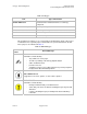
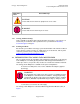
Canopy T1/E1 Multiplexer Admonition Label September 2004 T1/E1 Multiplexer FPGA Version 3.4 General Message CAUTION! a notice that the risk of harm to equipment or service exists. WARNING! a notice that the risk of harm to person exists. 1.1.5 Getting Additional Help Help is available for problems with supported products and features. The sequence of actions that you should take if these problems arise is provided under Obtaining Technical Support on Page 65. 1.1.
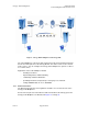
Canopy T1/E1 Multiplexer September 2004 T1/E1 Multiplexer FPGA Version 3.4 Figure 1: Canopy T1/E1 Multiplexer with Canopy BHs The T1/E1 Multiplexer converts the data stream from T1/E1 ports into Ethernet packets that are then transported over the Canopy BH link. This device can be used to extend T1/E1 services. You can configure the Canopy T1/E1 Multiplexer to operate as either a T1 or an E1 device. Applications of the T1/E1 Multiplexer include 1.2.1 ◦ obviating leased lines.
Canopy T1/E1 Multiplexer 1.2.2 September 2004 T1/E1 Multiplexer FPGA Version 3.4 Standards The Canopy T1/E1 Multiplexer conforms to the following standards: 1.2.3 ◦ G.703 ◦ TR-AT&TG2411 ◦ G.823 ◦ IEEE 802.3 ◦ G.824 ◦ EMC Class A compliance – EN 55022 Class A ◦ ANSI T1.403 IDU Physical Description The unit provides a compact, simple to configure, and easily scalable solution for transporting T1/E1 services over Canopy wireless Ethernet-based networks. 1.2.
Canopy T1/E1 Multiplexer September 2004 T1/E1 Multiplexer FPGA Version 3.4 Figure 3: Rear panel with standard 110-v source power supply WARNING! An external AC surge suppression device must be used with the Canopy T1/E1 Multiplexer. For infrastructure installations, Canopy Engineering recommends an AC line surge suppression unit that meets the standard IEC 801-5 (EN61000-4-5) Maximum Surge Voltage (1.2x50µsec) 6 KV.
Canopy T1/E1 Multiplexer September 2004 T1/E1 Multiplexer FPGA Version 3.4 Figure 5: Rear panel with optional −48 v power supply adapter for battery backup The recommended sequence of connection is: 1. Connect a PBX or TDM CPE to the T1/E1 port(s). (See Figure 2 on Page 11.) 2. Connect the Ethernet cable from the Canopy Backhaul Module to the jack labeled Canopy. (See Figure 2 on Page 11.) 3. Connect the selected power adapter to the T1/E1 Multiplexer. (See Figure 3 and Figure 4.) 4.
Canopy T1/E1 Multiplexer 1.2.5 September 2004 T1/E1 Multiplexer FPGA Version 3.4 Front Panel The control port and indicator LEDs are located on the front panel of the unit. Figure 6: Canopy T1/E1 Multiplexer front panel Status LEDS The status indicator LEDS on the front of the Canopy T1/E1 Multiplexer are listed in Table 3.
Canopy T1/E1 Multiplexer September 2004 T1/E1 Multiplexer FPGA Version 3.4 LED LED indicator descriptions LAN ACT OFF when no activity; BLINKING when frames are being transmitted or received on the line T1/E1 Sync ON when the port is synchronized (no alarm); OFF when Loss of signal (LOS); one LED for each T1/E1 1.2.6 Features The Canopy T1/E1 Multiplexer 1.2.7 ◦ installs easily. ◦ multiplexes up to 4 T1 or 3 E1 circuits onto a Canopy Backhaul point-to-point link.
Canopy T1/E1 Multiplexer September 2004 T1/E1 Multiplexer FPGA Version 3.4 Technical Specifications The following tables list the technical specifications for the Canopy T1/E1 Multiplexer. Table 5: T1 port specifications Specification Description Ports 1, 2, 3, and 4 Compliance ANSI T1.403 Connector RJ-45, 8-pin T1 Data Rate 1.55 Mbps T1 Line Code B8ZS, AMI Line Impedance Balanced: 100 ohms Signal levels Receive: 0 to -27 dB Transmit: +2.
Canopy T1/E1 Multiplexer September 2004 T1/E1 Multiplexer FPGA Version 3.4 Table 8: E1 framing specifications Specification Description Compliance ITU-T G.703 Framing transparent Signaling transparent Table 9: Local terminal and control interface specifications 1.3 Specification Description Type RS-232 via DB-9 Female Connector Mode DTE Baud Rate 19.2 kbps CONFIGURATION SETTINGS FROM CANOPY FACTORY 1.3.
Canopy T1/E1 Multiplexer 1.3.2 September 2004 T1/E1 Multiplexer FPGA Version 3.4 License Keys Each Canopy T1/E1 Multiplexer is purchased and shipped as 1-port enabled or 4-port enabled. You can upgrade any pair of 1-port enabled Canopy T1/E1 Multiplexers through the purchase and installation of 1.3.3 ◦ two keys, one per unit, to transform both to 2-port enabled. ◦ four keys, two per unit, to transform both to 3-port enabled. ◦ six keys, three per unit, to transform both to 4-port enabled.
Canopy T1/E1 Multiplexer 1.5.1 September 2004 T1/E1 Multiplexer FPGA Version 3.4 Channel Modes T1 Channel Mode While in T1 mode, the Canopy T1/E1 Multiplexer operates as a DSX-1 interface in a DSU channel mode. There are no user options to change this mode. The DSU channel mode can operate within five line lengths, each providing compensation for the length of the T1 line. The line lengths are: ◦ 0-133 ft. / 0.6dB ◦ 134-266 ft. / 1.2dB ◦ 267-399 ft. / 1.8dB ◦ 400-533 ft. / 2.4dB ◦ 534-655 ft.
Canopy T1/E1 Multiplexer September 2004 T1/E1 Multiplexer FPGA Version 3.4 For E1 mode, the Canopy T1/E1 Multiplexer supports the following: ◦ Transparent support of the E1 channel ◦ AMI ◦ HDB3 ◦ up to three ports Alternate Mark Inversion (AMI) The template of the DS-1 signal is bipolar. This means that a plus voltage, a zero voltage, and a minus voltage are important to the coding of the signal. The code that is used in T1 is called Alternate Mark Inversion (AMI).
Canopy T1/E1 Multiplexer September 2004 T1/E1 Multiplexer FPGA Version 3.4 The receiver will use these violations for synchronization. The receiver recognizes that the transmitted bit stream containing the two AMI violations is not true data. The B8ZS is the standard for “Clear Channel Capability” and is part of ANSI.T1.403-1989. High Density Bipolar Order Three Encoding High Density Bipolar Order 3 Encoding (HDB3) is a bipolar signaling technique that is based on Alternate Mark Inversion (AMI).
Canopy T1/E1 Multiplexer September 2004 T1/E1 Multiplexer FPGA Version 3.4 Table 10: Frequency off-set by clock type Clock Type Frequency Off-set (accuracy over 24 hours) Stratum 1 Clock 1 x10 Stratum 2 Clock -11 Time to First Frame Slip Application 1 every 72 days Gateway Office 1x10⁻¹⁰ 1 every 3.5 hours Toll Center Stratum 3 Clock 3.7x10⁻⁷ 1 every 6 minutes or 255 in 24 hours Central Office Stratum 4 Clock 3.
Canopy T1/E1 Multiplexer September 2004 T1/E1 Multiplexer FPGA Version 3.4 Loss of Clock Signal Should the Master port not be able to track the incoming T1/E1 bit stream due to a loss of signal, then the unit will use the Secondary port as the clock source. Once the Master T1 recovers synchronization by locking onto the signal, the unit will revert to using the Master port as the clock source.
Canopy T1/E1 Multiplexer September 2004 T1/E1 Multiplexer FPGA Version 3.4 Figure 9: Slave timing set to Recovered mode Network Timing Scenarios Typically, when connecting two T1 devices, one end is set as the master clock source and the other end is set as the slave clock source. The slave device takes the timing information from the master clock source. The slave device then synchronizes its clocks with the master. This is shown in Figure 10.
Canopy T1/E1 Multiplexer September 2004 T1/E1 Multiplexer FPGA Version 3.4 In a scenario where T1/E1 devices are configured with an external master clock source, each Canopy T1/E1 Multiplexer should be configured in Loopback Timing Mode. Each Canopy T1/E1 Multiplexer will take the timing signal from the incoming T1/E1, derive the clock and then return the clock to the T1/E1 device.
Canopy T1/E1 Multiplexer 1.5.6 September 2004 T1/E1 Multiplexer FPGA Version 3.4 VLAN Support The Canopy T1/E1 Multiplexer fully supports customer VLAN traffic. The Canopy T1/E1 Multiplexer has an increased maximum Ethernet packet size of 1600 bytes. Typically, the maximum packet size is 1518 bytes for Ethernet traffic, however VLAN traffic adds an extra 4 bytes for the VLAN tag as in the 802.1Q protocol.
Canopy T1/E1 Multiplexer September 2004 T1/E1 Multiplexer FPGA Version 3.4 2 INSTALLING AND CONFIGURING YOUR CANOPY T1/E1 MULTIPLEXERS 2.1 SAFETY INFORMATION 2.1.1 Compliance It is the responsibility of the installer to be sure that all building and safety codes are met and that the installation is complete and secure. For Canadian installations, the entire equipment installation must comply with Canadian Standard CSA 22.2, No. 60950, Safety of Information Technology Equipment.
Canopy T1/E1 Multiplexer September 2004 T1/E1 Multiplexer FPGA Version 3.4 WARNING! Substitution of the power supply may impair intrinsic safety. The Canopy T1/E1 Multiplexer must be used with Model Number TR10R033 manufactured by Cincon Electronics Co., Ltd. 2.2 INSTALLATION PROCEDURES 2.2.1 Package Contents Verify the contents shipped against the packing list for the box. You should have received the following: 2.2.
Canopy T1/E1 Multiplexer September 2004 T1/E1 Multiplexer FPGA Version 3.4 Figure 11: Front panel and front bezel removed 3. Place the Canopy T1/E1 Multiplexer behind the desired Rack Panel mounting hole. NOTE: The Rack Panel will support three (3) Canopy T1/E1 Multiplexers. 4. Place the Front Panel on the front of the Rack Panel opening, positioning the Rack Panel Spacer between the two panels. 5. Insert the front panel mounting screws through the screw holes. 6. Tighten screws. 7.
Canopy T1/E1 Multiplexer Canopy BH RJ-45 connector September 2004 T1/E1 Multiplexer FPGA Version 3.4 Pin LAN RJ-45 connector Color TD+ 1 TD+ White/Green TD- 2 TD- Green RD+ 3 RD+ White/Orange Nc 4 Not used Blue Nc 5 Not used White/blue RD 6 RD Orange Nc 7 Not used White/brown Nc 8 Not used brown Figure 12: RJ-45 Ethernet connection pin-outs (LAN side) Perform this procedure to connect the cables to the T1/E1 unit. Procedure 2: Connecting cables to T1/E1 unit 1.
Canopy T1/E1 Multiplexer September 2004 T1/E1 Multiplexer FPGA Version 3.4 WARNING! Disconnect power before proceeding. Follow this procedure to connect the supplied AC adapter (+3.3 v DC power source). Procedure 3: Connecting the AC adapter (+3.3 v DC power source) 1. Connect the AC adapter to a surge suppression device that meets the standard specified under Power Supply Unit on Page 27. 2. Connect the surge suppression device to the building AC power source. 3.
Canopy T1/E1 Multiplexer September 2004 T1/E1 Multiplexer FPGA Version 3.4 Figure 13: Rear panel Option 2: −48 v DC polarity 3. Connect the power cables to an external −48 v DC supply. end of procedure 2.3 INITIAL CONFIGURATION PROCEDURES 2.3.1 Installing Software from the CD‐ROM Procedure 5: Installing Software from the CD-ROM Follow these steps to install the software that is provided by Motorola Canopy on the CDROM onto your PC. 1. Load software onto your PC.
Canopy T1/E1 Multiplexer 2.3.2 September 2004 T1/E1 Multiplexer FPGA Version 3.4 Using EMS Software to Configure the Unit An intuitive graphic unit interface (GUI) provides a user-friendly graphical display that allows easy-to-follow steps to configure the unit. Fault isolation, statistics and events gathering are available. The GUI simplifies field installation. Examples of drop-down menus are provided in Figure 14 and Figure 15.
Canopy T1/E1 Multiplexer 2.3.3 September 2004 T1/E1 Multiplexer FPGA Version 3.4 Accessing the CLI using a PC + HyperTerminal The Command Line Interface (CLI) is accessed using a PC with that includes a terminal emulation package such as HyperTerminal®. NOTE: The device is only accessible through the serial port. 2.3.4 Configuring the Canopy T1/E1 Multiplexer using the CLI Before you use the CLI to configure the Canopy T1/E1 Multiplexer, you must configure the PC serial port.
Canopy T1/E1 Multiplexer September 2004 T1/E1 Multiplexer FPGA Version 3.4 Figure 16: Command Line Interface window 2.3.5 Creating a Login Account The system is shipped with default setting for the Administrator account. The account is active, but it is recommended you change the password for this account.
Canopy T1/E1 Multiplexer September 2004 T1/E1 Multiplexer FPGA Version 3.4 NOTE: The default administrator account username is admin. The default administrator account password is 123. You cannot change the username. However, you can change the password at any time. If you forget your password, reset the system back to the default account and password by logging in, using the safety account. The safety account username is safety. The safety account password is SAFE_qwe.
Canopy T1/E1 Multiplexer September 2004 T1/E1 Multiplexer FPGA Version 3.4 10. At the username prompt, enter admin. 11. At the password prompt, enter your new password. end of procedure 2.4.3 Select Line Type T1 or E1 Procedure 8: Selecting line type T1 or E1 using the CLI Follow this procedure to select the appropriate line type using the CLI manager. Action Log in Steps Press Enter. At the username prompt, enter admin. At the password prompt, enter password. Get line type Enter get line type.
Canopy T1/E1 Multiplexer 2.4.4 September 2004 T1/E1 Multiplexer FPGA Version 3.4 Select Line Coding Procedure 9: Configuring line coding using the CLI Follow this procedure to select the appropriate line code using the CLI manager. Action Log in Steps Press Enter. At the username prompt, enter admin. At the password prompt, enter password.
Canopy T1/E1 Multiplexer 2.4.5 September 2004 T1/E1 Multiplexer FPGA Version 3.4 Configure Ports Procedure 10: Configuring the Ethernet ports using the CLI Perform this procedure to configure the Ethernet ports using the CLI manager. NOTE: Both Ethernet ports operate at 100 Mbps Full Duplex. They will not operate at 10 Mbps or at half duplex. Action Log in Steps Press Enter. At the username prompt, enter admin. At the password prompt, enter password.
Canopy T1/E1 Multiplexer September 2004 T1/E1 Multiplexer FPGA Version 3.4 Procedure 11: Configuring the T1 ports using the CLI Follow this procedure to configure the T1 ports from the CLI manager. Action Log in Steps Press Enter. At the username prompt, enter admin. At the password prompt, enter password. Set T1 line length NOTE: If the incorrect line length is selected, the result could be decreased T1 quality or echo on voice lines. The default length is 133 ft.
Canopy T1/E1 Multiplexer September 2004 T1/E1 Multiplexer FPGA Version 3.4 Action Set timing mode Steps NOTE: Timing mode applies to all four T1 lines. Loopback mode loops the T1/E1 Tx clock to the T1/E1 Rx. Recovered mode recovers the T1/E1 clock from the incoming T1/E1 over Ethernet bit stream (recovers the clock from the far end T1/E1). The default timing mode is Recovered. Enter set clock source [loopback/recovered] where [loopback/recovered] represents the clock timing mode.
Canopy T1/E1 Multiplexer September 2004 T1/E1 Multiplexer FPGA Version 3.4 Procedure 12: Configuring the E1 ports using the CLI Follow this procedure to configure the E1 ports from the CLI manager. Action Log in Steps Press Enter. At the username prompt, enter admin. At the password prompt, enter password. Set E1 line length NOTE: If the incorrect line length is selected, the result could be decreased E1 quality or echo on voice lines. The default length is 133 ft.
Canopy T1/E1 Multiplexer September 2004 T1/E1 Multiplexer FPGA Version 3.4 Action Set timing mode Steps NOTE: Timing mode applies to all four E1 lines. Loopback mode loops the T1/E1 Tx clock to the T1/E1 Rx. Recovered mode recovers the T1/E1 clock from the incoming T1/E1 over Ethernet bit stream (recovers the clock from the far end T1/E1). The default timing mode is Recovered.
Canopy T1/E1 Multiplexer 2.4.6 September 2004 T1/E1 Multiplexer FPGA Version 3.4 Configure Timing Before the timing may be configured, you need to determine the network timing scheme to be used. You also need to identify the master and slave devices for the end-user PBX equipment. Procedure 13: Configuring timing using the CLI Action Log in Steps Press Enter. At the username prompt, enter admin. At the password prompt, enter password.
Canopy T1/E1 Multiplexer September 2004 T1/E1 Multiplexer FPGA Version 3.4 Action Set timing mode Steps NOTE: Timing mode applies to all four E1 lines. Loopback mode loops the T1/E1 Tx clock to the T1/E1 Rx. Recovered mode recovers the T1/E1 clock from the incoming T1/E1 over Ethernet bit stream (recovers the clock from the far end T1/E1). The default timing mode is Recovered.
Canopy T1/E1 Multiplexer September 2004 T1/E1 Multiplexer FPGA Version 3.4 Figure 17: Login dialogue box Once you are successfully logged in, the T1/E1 Multiplexer EMS Main Menu opens (shown in Figure 18).
Canopy T1/E1 Multiplexer September 2004 T1/E1 Multiplexer FPGA Version 3.4 Figure 18: T1/E1 Multiplexer EMS main menu end of procedure NOTE: You can access CLI commands by selecting File→Command Line Terminal from the EMS Main menu.
Canopy T1/E1 Multiplexer 2.5.2 September 2004 T1/E1 Multiplexer FPGA Version 3.4 Changing the Administrator Password There is only one account for the Canopy T1/E1 Multiplexer—the administrator account. The username may not be changed, however the password may be changed at any time. Figure 19: Change Password dialogue box Procedure 15: Changing Administrator password using the EMS Use this procedure to change the password from the EMS. 1. Select File→Change password from the main menu.
Canopy T1/E1 Multiplexer 2.5.3 September 2004 T1/E1 Multiplexer FPGA Version 3.4 Select Line Type T1 or E1 Procedure 16: Selecting line type T1 or E1 using the EMS Follow these steps to configure line coding for the Canopy T1/E1 Multiplexer from the EMS. NOTE: Selecting either T1 or E1 will configure all 4 channels. 1. From main menu EMS, select the Configuration (Config) option. 2. Select Configure Line Type. RESULT: The Line Config dialogue box opens. 3. Click ↓.
Canopy T1/E1 Multiplexer September 2004 T1/E1 Multiplexer FPGA Version 3.4 Procedure 18: Configuring E1 line coding using the EMS Follow these steps to configure line coding from the EMS. 1. From main menu EMS, select the Configuration (Config) option. 2. Select Configure E1. RESULT: The E1 Config dialogue box opens. 3. Click ↓. RESULT: The dropdown list to specify the coding technique E1 channel opens. 4. Click on the appropriate line coding technique for the E1channel being configured.
Canopy T1/E1 Multiplexer September 2004 T1/E1 Multiplexer FPGA Version 3.4 4. Click ↓ for Coding. 5. Select the coding technique for the channel. NOTE: For T1, you must select either B8ZS or AMI. 6. Click on the tab for the next Channel to configure. NOTE: If the system has been reset, clicking the Refresh button will replace the displayed values with currently-programmed values. 7. Repeat steps 1 and 2 to configure each channel. 8. Click ↓ for Master Clock Reference Line. 9.
Canopy T1/E1 Multiplexer September 2004 T1/E1 Multiplexer FPGA Version 3.4 10. Click on the radio button to indicate whether the clock source is loopback mode or recovered mode. NOTE: The clock source applies to all four channels. Loopback mode loops the Tx clock back to the Rx. Recovered mode recovers the clock from the incoming T1/E1 over Ethernet-bitstream (from the far end T1/E1). 11. Select Close to close the dialogue box once all channels are configured.
Canopy T1/E1 Multiplexer September 2004 T1/E1 Multiplexer FPGA Version 3.4 3 MANAGING YOUR CANOPY T1/E1 MULTIPLEXERS 3.1 REMOTE MANAGEMENT THROUGH CONTROL PORT The CONTROL port in the front panel (shown in Figure 6 on Page 14) provides the capability to remotely manage the Canopy T1/E1 Multiplexer. To do so requires an Ethernet to RS-232 converter. An example of such a converter is available at http://www.precidia.com/products/product1.html.
Canopy T1/E1 Multiplexer 3.2 September 2004 T1/E1 Multiplexer FPGA Version 3.4 T1/E1 ALARMS Each T1/E1 channel has alarms for line code violation (BPV), receive loss of signal (LOS), and alarm indication signal (AIS) detection. Follow these steps to display the alarms using the CLI. Procedure 23: Displaying the alarms using the CLI Action Log in Steps Press Enter. At the username prompt, enter admin. At the password prompt, enter password. View T1/E1 Alarms Enter get alarms.
Canopy T1/E1 Multiplexer September 2004 T1/E1 Multiplexer FPGA Version 3.4 Follow these steps to display the T1/E1 alarms using the EMS. Procedure 24: Displaying alarms using the EMS 1. Select the Alarms→T1/E1 Alarms menu. RESULT: The T1/E1 Alarms window pops up as shown in Figure 21. 2. Select the desired T1/E1 Channel (1 through 4). end of procedure NOTES: 1. The T1/E1 alarms will be displayed, with a green light meaning no current alarms and a red light meaning that there is a current alarm.
Canopy T1/E1 Multiplexer 3.3 September 2004 T1/E1 Multiplexer FPGA Version 3.4 SYSTEM RESET Follow the steps below to reset the system from the CLI. Procedure 25: Resetting the system using the CLI Action Log in Steps Press Enter. At the username prompt, enter admin. At the password prompt, enter password. Reset system Enter reset. RESULT: The system responds Resetting, then immediately resets both Ethernet Interfaces and all 4 T1/E1 interfaces without asking for a confirmation.
Canopy T1/E1 Multiplexer 3.4 September 2004 T1/E1 Multiplexer FPGA Version 3.4 T1/E1 LOOPBACK Each of the 4 T1/E1s can be placed in loopback mode for testing and maintenance purposes. This provides a bi-directional loopback on the T1/E1 interface. The near end T1/E1 Transmit is looped back to the near end Receive, and the far end T1/E1 transmit that arrives over the BH Ethernet port is looped back to the far end Receive.
Canopy T1/E1 Multiplexer 3.4.1 September 2004 T1/E1 Multiplexer FPGA Version 3.4 Invoking a T1/E1 Loopback using the CLI Follow the steps below to invoke a T1/E1 Loopback from the CLI. Procedure 27: Invoking a T1/E1 loopback using the CLI Action Steps Log in Press Enter. At the username prompt, enter admin. At the password prompt, enter password. Set T1/E1 into Loopback Mode Enter set line loopback [1/2/3/4] [on/off] where [1/2/3/4] represents T1/E1 ports 1 through 4. on will enable T1/E1 loopback.
Canopy T1/E1 Multiplexer 3.5 September 2004 T1/E1 Multiplexer FPGA Version 3.4 MEASUREMENTS FROM DIAGNOSTICS A unit-based comparison of diagnostic measurements is provided in Table 13.
Canopy T1/E1 Multiplexer September 2004 T1/E1 Multiplexer FPGA Version 3.4 3. Click Browse to find the new FPGA firmware that your authorized Canopy distributor or reseller provided. 4. Select the file to download. NOTE: Typically the filename has the format Vx_y.bin (for example, V3_4.bin). 5. Click Download. RESULT: The status bar indicates the progress of the download process. IMPORTANT! During the download process, do not interrupt the download process. 6. Wait until the download is complete. 7.
Canopy T1/E1 Multiplexer 3.7 September 2004 T1/E1 Multiplexer FPGA Version 3.4 LICENSE KEY UPGRADES As previously described, you can transform any single-port enabled Canopy T1/E1 Multiplexer into a 2-port, 3-port, or 4-port multiplexer through the purchase and installation of license keys from your Canopy distributor. Procedure 30: Installing a license key to enable an additional port To install a license key on a Canopy T1/E1 Multiplexer, perform the following steps. 1.
Canopy T1/E1 Multiplexer September 2004 T1/E1 Multiplexer FPGA Version 3.4 Figure 28: Invalid key entry window NOTE: At any later date, you can confirm the number of enabled ports as follows. 4. From the main menu, select Config→Canopy T1/E1 Mux. RESULT: The Canopy T1/E1 Mux Configuration window opens, as shown in Figure 29. Figure 29: Canopy T1/E1 Mux Configuration window 5. In the lower right quadrant of the window, find the Enabled T1/E1 Ports block.
Canopy T1/E1 Multiplexer 3.8 September 2004 T1/E1 Multiplexer FPGA Version 3.4 TERMS OF WARRANTY 3.8.1 Software License Terms and Conditions ONLY OPEN THE PACKAGE, OR USE THE SOFTWARE AND RELATED PRODUCT IF YOU ACCEPT THE TERMS OF THIS LICENSE. BY BREAKING THE SEAL ON THIS DISK KIT / CDROM, OR IF YOU USE THE SOFTWARE OR RELATED PRODUCT, YOU ACCEPT THE TERMS OF THIS LICENSE AGREEMENT.
Canopy T1/E1 Multiplexer September 2004 T1/E1 Multiplexer FPGA Version 3.4 MOTOROLA OR AN AGENT THEREOF SHALL CREATE A WARRANTY OR IN ANY WAY INCREASE THE SCOPE OF THIS WARRANTY. MOTOROLA DOES NOT WARRANT ANY SOFTWARE THAT HAS BEEN OPERATED IN EXCESS OF SPECIFICATIONS, DAMAGED, MISUSED, NEGLECTED, OR IMPROPERLY INSTALLED. BECAUSE SOME JURISDICTIONS DO NOT ALLOW THE EXCLUSION OR LIMITATION OF IMPLIED WARRANTIES, THE ABOVE LIMITATIONS MAY NOT APPLY TO YOU. Limitation of Remedies and Damages.
Canopy T1/E1 Multiplexer September 2004 T1/E1 Multiplexer FPGA Version 3.4 process, will be submitted for non-binding mediation, prior to initiation of any formal legal process. Cost of mediation will be shared equally.
Canopy T1/E1 Multiplexer September 2004 T1/E1 Multiplexer FPGA Version 3.4 6. Verify that the Canopy configuration files match the last known good (baseline) Canopy configuration files captured in site log book. 7. Verify connectivity (physical cabling). 8. At the SM level, minimize your network configuration (remove home network devices to help isolate problem). 9. Perform the site verification checklist. 10. Check FAQs to see whether the problem and a solution are present. 11.
Canopy T1/E1 Multiplexer September 2004 T1/E1 Multiplexer FPGA Version 3.4 4 CANOPY T1/E1 MULTIPLEXER REFERENCE INFORMATION 4.1 CLI COMMANDS TO GET STATUS INFORMATION Desired Action Get Canopy-side Ethernet autonegotiation Syntax, Response, and Description Enter get canopy port auto negotiation The system responds Canopy port auto-negotiation is: [on/off] Gets the auto-negotiation mode for the Canopy BH Ethernet port. If auto negotiation is set to OFF, the port will be forced to 100 Mbps Full Duplex.
Canopy T1/E1 Multiplexer Desired Action Get T1 line length September 2004 T1/E1 Multiplexer FPGA Version 3.4 Syntax, Response, and Description Enter get line [1/2/3/4] length where [1/2/3/4] represents T1 ports 1 through 4. The system responds Line [1/2/3/4] length [0-133 / 0.6 dB; 133-266 / 1.2 dB; 266-399 / 1.8 dB; 399-533 / 2.4 dB; 533-655 / 3.0 dB] Gets the T1 line length. The units are in feet in decibels.
Canopy T1/E1 Multiplexer Desired Action Get the timing mode September 2004 T1/E1 Multiplexer FPGA Version 3.4 Syntax, Response, and Description Enter get clock source The system responds Clock source set to [loopback/recovered] Gets the T1 timing mode. This timing mode applies for all four T1 lines. Loopback mode means to take the T1 Tx clock and loop it back to the T1 Rx.
Canopy T1/E1 Multiplexer Desired Action View T1/E1 Alarms September 2004 T1/E1 Multiplexer FPGA Version 3.
Canopy T1/E1 Multiplexer Desired Action Get FPGA Revision September 2004 T1/E1 Multiplexer FPGA Version 3.4 Syntax, Response, and Description Enter get fpga revision The system responds FPGA revision is: x.y.z Get the revision (version number) of the Canopy T1/E1 FPGA. The FPGA controls the T1 parameters. 4.
Canopy T1/E1 Multiplexer 4.2.2 September 2004 T1/E1 Multiplexer FPGA Version 3.4 Department of Communications – Canada Canadian Compliance Statement This class B Digital apparatus meets all the requirements of the Canadian InterferenceCausing Equipment Regulations. This device complies with RSS-210 of Industry Canada.
Canopy T1/E1 Multiplexer 4.4 September 2004 T1/E1 Multiplexer FPGA Version 3.4 REFERENCES This document refers to the following documents: Issue 3 ◦ American National Standards Institute. ANSI T1.101-1999 – Telecommunication Synchronization Interface Standards. ◦ American National Standards Institute. ANSI T1.105.09-1996 – Synchronous Optical Network (SONET) Network Element Timing and Synchronization. ◦ American National Standards Institute. ANSI T1.