
Switch User Guide

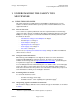
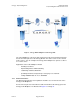
Table Of Contents
- UNDERSTANDING THE CANOPY T1/E1 MULTIPLEXER
- Status LEDS
- Physical Specifications
- Technical Specifications
- T1 Channel Mode
- E1 Channel Mode
- Alternate Mark Inversion (AMI)
- The 1 in 15 Requirement (AMI)
- Binary Eight Zero Substitution Coding
- High Density Bipolar Order Three Encoding
- Master and Secondary Clocks
- Loss of Clock Signal
- Timing Modes
- Loopback Timing Mode
- Recovered Timing Mode
- Network Timing Scenarios
- INSTALLING AND CONFIGURING YOUR CANOPY T1/E1 MULTIPLEXERS
- MANAGING YOUR CANOPY T1/E1 MULTIPLEXERS
- CANOPY T1/E1 MULTIPLEXER REFERENCE INFORMATION
- Canadian Compliance Statement
- Statement of Compliance
Canopy T1/E1MultiplexerSeptember2004
T1/E1MultiplexerFPGAVersion3.4
Page10 of 73
Figure 1: Canopy T1/E1 Multiplexer with Canopy BHs
The T1/E1 Multiplexer converts the data stream from T1/E1 ports into Ethernet packets
that are then transported over the Canopy BH link. This device can be used to extend
T1/E1 services. You can configure the Canopy T1/E1 Multiplexer to operate as either a
T1 or an E1 device.
Applications of the T1/E1 Multiplexer include
◦ obviating leased lines.
◦ implementing wireless PBX networking.
◦ establishing cellular backhaul links.
◦ providing homeland security backup or emergency voice networks.
◦ routing LAN/WAN data on excess bandwidth.
1.2.1 EthernetInterface
The Ethernet physical layer auto-negotiation should be set to on for both sides of the
Canopy T1/E1 Multiplexer.
RJ-45 connector pin-outs for the Ethernet cable from the BH to the Canopy port of the
Canopy T1/E1 Multiplexer are illustrated in Figure 12 on Page 30.
Issue3