
Switch User Guide
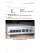

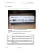
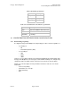
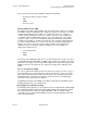
Table Of Contents
- UNDERSTANDING THE CANOPY T1/E1 MULTIPLEXER
- Status LEDS
- Physical Specifications
- Technical Specifications
- T1 Channel Mode
- E1 Channel Mode
- Alternate Mark Inversion (AMI)
- The 1 in 15 Requirement (AMI)
- Binary Eight Zero Substitution Coding
- High Density Bipolar Order Three Encoding
- Master and Secondary Clocks
- Loss of Clock Signal
- Timing Modes
- Loopback Timing Mode
- Recovered Timing Mode
- Network Timing Scenarios
- INSTALLING AND CONFIGURING YOUR CANOPY T1/E1 MULTIPLEXERS
- MANAGING YOUR CANOPY T1/E1 MULTIPLEXERS
- CANOPY T1/E1 MULTIPLEXER REFERENCE INFORMATION
- Canadian Compliance Statement
- Statement of Compliance
Canopy T1/E1MultiplexerSeptember2004
T1/E1MultiplexerFPGAVersion3.4
Page11 of 73
1.2.2 Standards
The Canopy T1/E1 Multiplexer conforms to the following standards:
◦ G.703 ◦ TR-AT&TG2411
◦ G.823 ◦ IEEE 802.3
◦ G.824 ◦ EMC Class A compliance – EN 55022 Class A
◦ ANSI T1.403
1.2.3 IDUPhysicalDescription
The unit provides a compact, simple to configure, and easily scalable solution for
transporting T1/E1 services over Canopy wireless Ethernet-based networks.
1.2.4 RearPanel
Interface connections and the power port are located on the rear panel of the unit.
Figure 2: Canopy T1/E1 Multiplexer rear panel
Issue3