
Switch User Guide
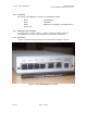
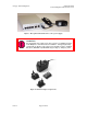
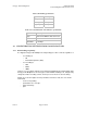
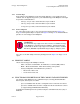
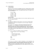
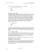
Table Of Contents
- UNDERSTANDING THE CANOPY T1/E1 MULTIPLEXER
- Status LEDS
- Physical Specifications
- Technical Specifications
- T1 Channel Mode
- E1 Channel Mode
- Alternate Mark Inversion (AMI)
- The 1 in 15 Requirement (AMI)
- Binary Eight Zero Substitution Coding
- High Density Bipolar Order Three Encoding
- Master and Secondary Clocks
- Loss of Clock Signal
- Timing Modes
- Loopback Timing Mode
- Recovered Timing Mode
- Network Timing Scenarios
- INSTALLING AND CONFIGURING YOUR CANOPY T1/E1 MULTIPLEXERS
- MANAGING YOUR CANOPY T1/E1 MULTIPLEXERS
- CANOPY T1/E1 MULTIPLEXER REFERENCE INFORMATION
- Canadian Compliance Statement
- Statement of Compliance
Canopy T1/E1MultiplexerSeptember2004
T1/E1MultiplexerFPGAVersion3.4
Page12 of 73
Figure 3: Rear panel with standard 110-v source power supply
WARNING!
An external AC surge suppression device must be used with the Canopy
T1/E1 Multiplexer. For infrastructure installations, Canopy Engineering
recommends an AC line surge suppression unit that meets the standard
IEC 801-5 (EN61000-4-5) Maximum Surge Voltage (1.2x50µsec) 6 KV.
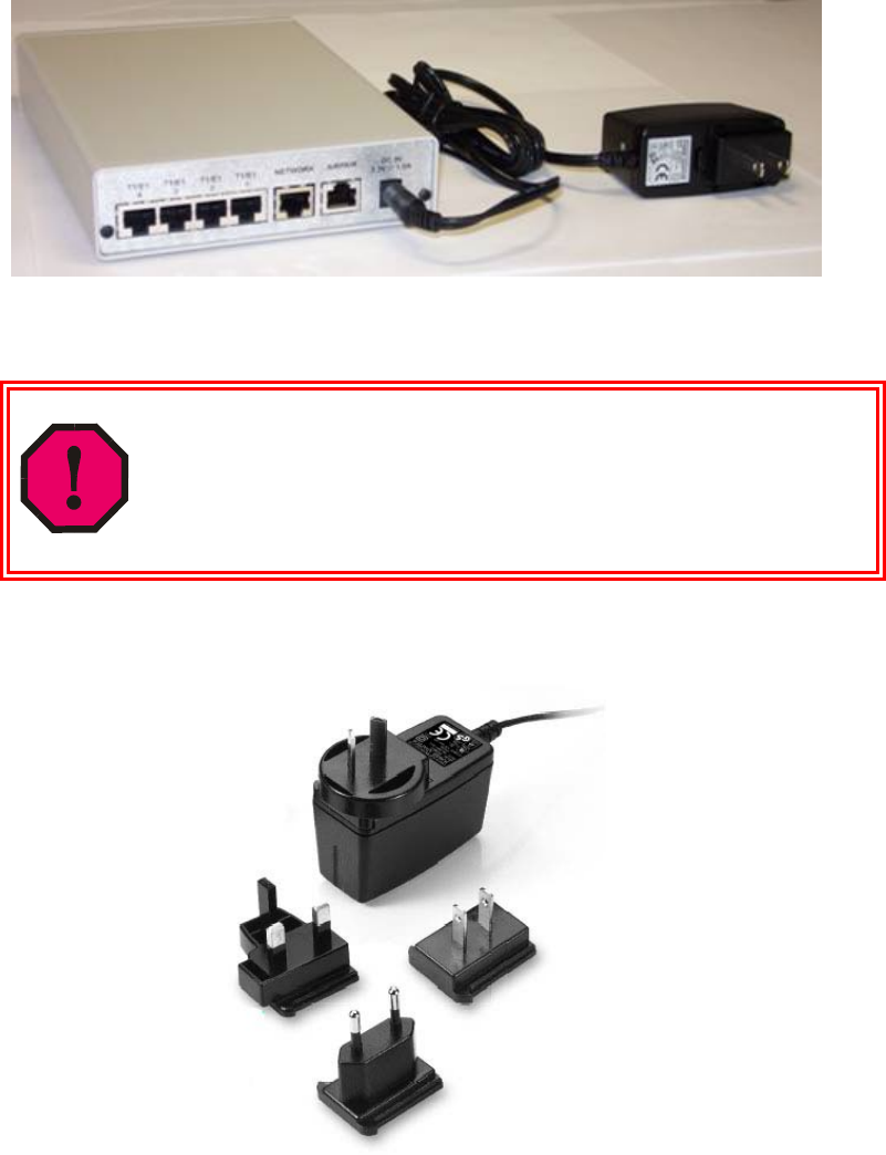
Figure 4: Standard adapters for global use
Issue3