
Switch User Guide
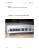
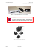
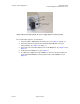
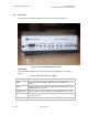
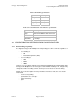
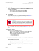
Table Of Contents
- UNDERSTANDING THE CANOPY T1/E1 MULTIPLEXER
- Status LEDS
- Physical Specifications
- Technical Specifications
- T1 Channel Mode
- E1 Channel Mode
- Alternate Mark Inversion (AMI)
- The 1 in 15 Requirement (AMI)
- Binary Eight Zero Substitution Coding
- High Density Bipolar Order Three Encoding
- Master and Secondary Clocks
- Loss of Clock Signal
- Timing Modes
- Loopback Timing Mode
- Recovered Timing Mode
- Network Timing Scenarios
- INSTALLING AND CONFIGURING YOUR CANOPY T1/E1 MULTIPLEXERS
- MANAGING YOUR CANOPY T1/E1 MULTIPLEXERS
- CANOPY T1/E1 MULTIPLEXER REFERENCE INFORMATION
- Canadian Compliance Statement
- Statement of Compliance
Canopy T1/E1MultiplexerSeptember2004
T1/E1MultiplexerFPGAVersion3.4
Page13 of 73
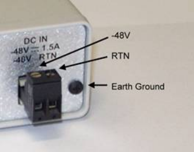
Figure 5: Rear panel with optional −48 v power supply adapter for battery backup
The recommended sequence of connection is:
1. Connect a PBX or TDM CPE to the T1/E1 port(s). (See Figure 2 on Page 11.)
2. Connect the Ethernet cable from the Canopy Backhaul Module to the jack
labeled Canopy. (See Figure 2 on Page 11.)
3. Connect the selected power adapter to the T1/E1 Multiplexer. (See Figure 3 and
Figure 4.)
4. Power the T1/E1 Multiplexer on. (See Figure 3.)
5. As required to configure the T1/E1 Multiplexer, connect a notebook computer to
the jack labeled CONTROL on the front panel of the T1/E1 Multiplexer. (See
Figure 6.)
Issue3