
Switch User Guide
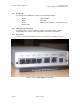
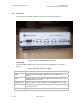
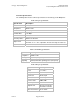
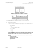
Table Of Contents
- UNDERSTANDING THE CANOPY T1/E1 MULTIPLEXER
- Status LEDS
- Physical Specifications
- Technical Specifications
- T1 Channel Mode
- E1 Channel Mode
- Alternate Mark Inversion (AMI)
- The 1 in 15 Requirement (AMI)
- Binary Eight Zero Substitution Coding
- High Density Bipolar Order Three Encoding
- Master and Secondary Clocks
- Loss of Clock Signal
- Timing Modes
- Loopback Timing Mode
- Recovered Timing Mode
- Network Timing Scenarios
- INSTALLING AND CONFIGURING YOUR CANOPY T1/E1 MULTIPLEXERS
- MANAGING YOUR CANOPY T1/E1 MULTIPLEXERS
- CANOPY T1/E1 MULTIPLEXER REFERENCE INFORMATION
- Canadian Compliance Statement
- Statement of Compliance
Canopy T1/E1MultiplexerSeptember2004
T1/E1MultiplexerFPGAVersion3.4
Page14 of 73
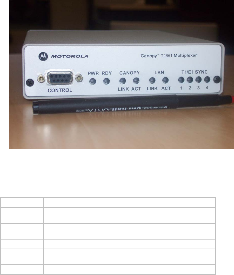
1.2.5 FrontPanel
The control port and indicator LEDs are located on the front panel of the unit.
Figure 6: Canopy T1/E1 Multiplexer front panel
Status LEDS
The status indicator LEDS on the front of the Canopy T1/E1 Multiplexer are listed in
Table 3.
Table 3: LED status indicator descriptions
LED
LED indicator descriptions
PWR ON when main power supply is OK; OFF when a malfunction is
detected
RDY ON when self-test is successfully completed; OFF during self-test; and
BLINKING when self-test fails
CANOPY LINK OFF when line is not active; ON when Canopy BH Ethernet line is OK
CANOPY ACT OFF when no activity; BLINKNG when frames are being transmitted or
received on the line
LAN LINK OFF when line is not active; ON when line is OK
Issue3