
Switch User Guide
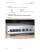
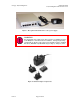
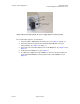
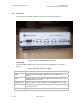
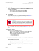
Table Of Contents
- UNDERSTANDING THE CANOPY T1/E1 MULTIPLEXER
- Status LEDS
- Physical Specifications
- Technical Specifications
- T1 Channel Mode
- E1 Channel Mode
- Alternate Mark Inversion (AMI)
- The 1 in 15 Requirement (AMI)
- Binary Eight Zero Substitution Coding
- High Density Bipolar Order Three Encoding
- Master and Secondary Clocks
- Loss of Clock Signal
- Timing Modes
- Loopback Timing Mode
- Recovered Timing Mode
- Network Timing Scenarios
- INSTALLING AND CONFIGURING YOUR CANOPY T1/E1 MULTIPLEXERS
- MANAGING YOUR CANOPY T1/E1 MULTIPLEXERS
- CANOPY T1/E1 MULTIPLEXER REFERENCE INFORMATION
- Canadian Compliance Statement
- Statement of Compliance

Canopy T1/E1MultiplexerSeptember2004
T1/E1MultiplexerFPGAVersion3.4
Page18 of 73
1.3.2 LicenseKeys
Each Canopy T1/E1 Multiplexer is purchased and shipped as 1-port enabled or 4-port
enabled. You can upgrade any pair of 1-port enabled Canopy T1/E1 Multiplexers through
the purchase and installation of
◦ two keys, one per unit, to transform both to 2-port enabled.
◦ four keys, two per unit, to transform both to 3-port enabled.
◦ six keys, three per unit, to transform both to 4-port enabled.
1.3.3 PowerAdapters
For connection to power sources, the 110-volt power supply pictured in Figure 3 on
Page 12 and the global adapter set pictured in Figure 4 on Page 12 are included with the
purchase of each Canopy T1/E1 Multiplexer.
WARNING!
An external AC surge suppression device must be used with the Canopy
T1/E1 Multiplexer. For infrastructure installations, Canopy Engineering
recommends an AC line surge suppression unit that meets the standard
IEC 801-5 (EN61000-4-5) Maximum Surge Voltage (1.2x50µsec) 6 KV.
The −48 v screw-down adapter for battery backup pictured in Figure 5 on Page 13 is an
option.
1.4 PRODUCTLABELS
Labels on the Canopy T1/E1 Multiplexer include
◦ ESN — Electronic Serial Number, the Media Access Control (MAC) address
◦ MSN — Model Serial Number, which allows tracking of the product
◦ Factory Configuration, which identifies the product as
− Master Unit or Slave Unit
− 1-Port Unit or 4-Port Unit
1.5 FUNCTIONALDESCRIPTIONOFTHECANOPYT1/E1MULTIPLEXER
The Canopy T1/E1 Multiplexer has a LAN Ethernet port, a Canopy Backhaul Module
Ethernet port, and four ports as follows:
◦ up to four available when the unit is configured for the T1 transmission scheme.
◦ up to three available when the unit is configured for the E1 transmission scheme
(to support Canopy BH20 Backhaul link traffic).
Configuration and management are provided using the command line interface (CLI) or
EMS GUI.
Issue3