
Switch User Guide
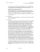
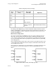
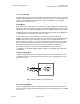
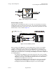
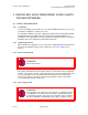
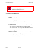
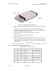
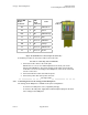
Table Of Contents
- UNDERSTANDING THE CANOPY T1/E1 MULTIPLEXER
- Status LEDS
- Physical Specifications
- Technical Specifications
- T1 Channel Mode
- E1 Channel Mode
- Alternate Mark Inversion (AMI)
- The 1 in 15 Requirement (AMI)
- Binary Eight Zero Substitution Coding
- High Density Bipolar Order Three Encoding
- Master and Secondary Clocks
- Loss of Clock Signal
- Timing Modes
- Loopback Timing Mode
- Recovered Timing Mode
- Network Timing Scenarios
- INSTALLING AND CONFIGURING YOUR CANOPY T1/E1 MULTIPLEXERS
- MANAGING YOUR CANOPY T1/E1 MULTIPLEXERS
- CANOPY T1/E1 MULTIPLEXER REFERENCE INFORMATION
- Canadian Compliance Statement
- Statement of Compliance

Canopy T1/E1MultiplexerSeptember2004
T1/E1MultiplexerFPGAVersion3.4
Page28 of 73
WARNING!
Substitution of the power supply may impair intrinsic safety. The
Canopy T1/E1 Multiplexer must be used with Model Number TR10R033
manufactured by Cincon Electronics Co., Ltd.
2.2 INSTALLATIONPROCEDURES
2.2.1 PackageContents
Verify the contents shipped against the packing list for the box. You should have received
the following:
◦ T1/E1 unit
◦ AC Power supply (Option 1 only)
◦ CD ROM (EMS GUI and the software download application)
2.2.2 PreparingforInstallationandSetup
Select the appropriate type of cable for connection to the Ethernet port of the Canopy
T1/E1 Multiplexer as follows:
◦ For connection to a LAN or a switch, a straight-through cable is required.
◦ For connection to the NIC card in a PC, a crossover cable is required.
◦ For connection to a PBX, a T1/E1 crossover cable is likely required. Refer to your
PBX installation instruction manual for specific requirements.
2.2.3 MountingtheCanopyT1/E1Multiplexer
Mounting option for the unit is either a desk mount or a rack mount. Follow this procedure
to affix the until to a rack mount:
Procedure 1: Affixing the Multiplexer to a rack mount
Remove the Front Panel by removing Front Panel Mounting Screws.
1. Remove the two screw posts from the DB-9 connector.
2. Remove Front Bezel and set aside.
Issue3