
Switch User Guide
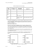
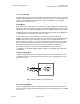
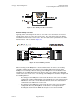
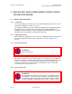
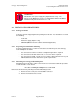
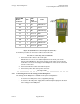
Table Of Contents
- UNDERSTANDING THE CANOPY T1/E1 MULTIPLEXER
- Status LEDS
- Physical Specifications
- Technical Specifications
- T1 Channel Mode
- E1 Channel Mode
- Alternate Mark Inversion (AMI)
- The 1 in 15 Requirement (AMI)
- Binary Eight Zero Substitution Coding
- High Density Bipolar Order Three Encoding
- Master and Secondary Clocks
- Loss of Clock Signal
- Timing Modes
- Loopback Timing Mode
- Recovered Timing Mode
- Network Timing Scenarios
- INSTALLING AND CONFIGURING YOUR CANOPY T1/E1 MULTIPLEXERS
- MANAGING YOUR CANOPY T1/E1 MULTIPLEXERS
- CANOPY T1/E1 MULTIPLEXER REFERENCE INFORMATION
- Canadian Compliance Statement
- Statement of Compliance
Canopy T1/E1MultiplexerSeptember2004
T1/E1MultiplexerFPGAVersion3.4
Page29 of 73
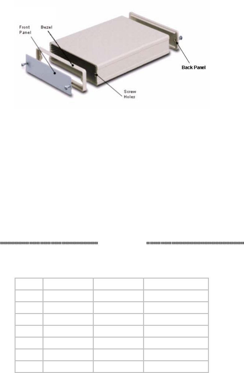
Figure 11: Front panel and front bezel removed
3. Place the Canopy T1/E1 Multiplexer behind the desired Rack Panel mounting
hole.
NOTE: The Rack Panel will support three (3) Canopy T1/E1 Multiplexers.
4. Place the Front Panel on the front of the Rack Panel opening, positioning the
Rack Panel Spacer between the two panels.
5. Insert the front panel mounting screws through the screw holes.
6. Tighten screws.
7. Insert the screw posts onto the DB-9 connector.
8. Tighten screw posts.
9. Mount the Canopy T1/E1 Multiplexer with the rack panel onto your rack unit.
Consult the product information supplied by the rack manufacturer for details.
NOTE: The front panel mounting screws should be 4-40 screws, between 3/8”
and 5/8” long.
end of procedure
2.2.4 ConnectingtheCanopyT1/E1Multiplexer
Table 12: T1/E1 port connector pin-out
Pin Designation Direction Function
1 RD(R) Input Receive data (ring)
2 RD(T) Input Receive data (tip)
3 FGND
4 TD(R) Output Transmit data (ring)
5 TD(T) Output Transmit data (tip)
6 FGND
7, 8 FGND Not connected
Issue3