
Switch User Guide
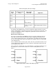
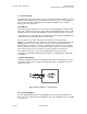
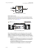
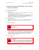
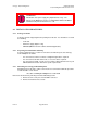
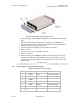
Table Of Contents
- UNDERSTANDING THE CANOPY T1/E1 MULTIPLEXER
- Status LEDS
- Physical Specifications
- Technical Specifications
- T1 Channel Mode
- E1 Channel Mode
- Alternate Mark Inversion (AMI)
- The 1 in 15 Requirement (AMI)
- Binary Eight Zero Substitution Coding
- High Density Bipolar Order Three Encoding
- Master and Secondary Clocks
- Loss of Clock Signal
- Timing Modes
- Loopback Timing Mode
- Recovered Timing Mode
- Network Timing Scenarios
- INSTALLING AND CONFIGURING YOUR CANOPY T1/E1 MULTIPLEXERS
- MANAGING YOUR CANOPY T1/E1 MULTIPLEXERS
- CANOPY T1/E1 MULTIPLEXER REFERENCE INFORMATION
- Canadian Compliance Statement
- Statement of Compliance
Canopy T1/E1MultiplexerSeptember2004
T1/E1MultiplexerFPGAVersion3.4
Page30 of 73
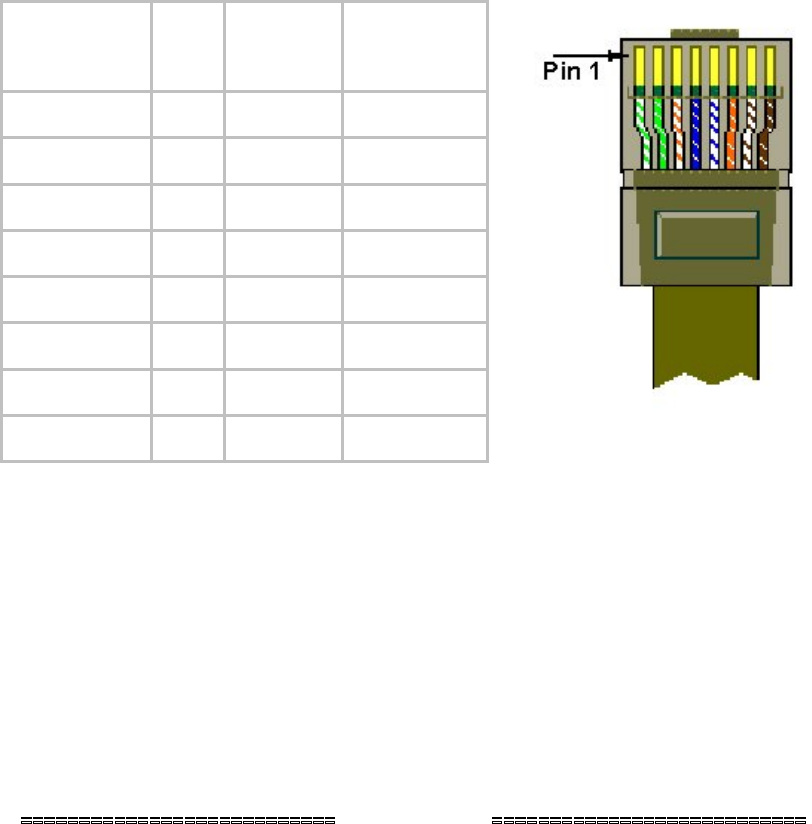
Canopy BH
RJ-45
connector
Pin
LAN
RJ-45
connector
Color
TD+ 1 TD+ White/Green
TD- 2 TD- Green
RD+ 3 RD+ White/Orange
Nc 4 Not used Blue
Nc 5 Not used White/blue
RD 6 RD Orange
Nc 7 Not used White/brown
Nc 8 Not used brown
Figure 12: RJ-45 Ethernet connection pin-outs (LAN side)
Perform this procedure to connect the cables to the T1/E1 unit.
Procedure 2: Connecting cables to T1/E1 unit
1. Connect the T1/E1 cables to the T1/E1 ports.
NOTE: There is a one-to-one relationship between the T1/E1 ports on the
Canopy T1/E1 Multiplexer. This means, that the T1/E1 cable connected to the
T1/E1 Port 1 on one of the Canopy T1/E1 Multiplexers, must also be connected
to Port 1 on the other.
2. Connect the Ethernet cables to the Ethernet ports.
3. Connect the power cable to the power connector.
end of procedure
2.2.5 ConnectingPowertotheCanopyT1/E1Multiplexer
The Canopy T1/E1 Multiplexer is available in two power configurations:
◦ an external 3.3-v DC power source (supplied by Canopy)
◦ an external −48 v DC power supply with a terminal strip that plugs into the back
of the Canopy T1/E1 Multiplexer.
Issue3