
Switch User Guide
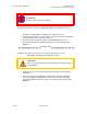
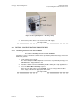
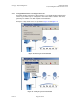
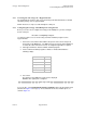
Table Of Contents
- UNDERSTANDING THE CANOPY T1/E1 MULTIPLEXER
- Status LEDS
- Physical Specifications
- Technical Specifications
- T1 Channel Mode
- E1 Channel Mode
- Alternate Mark Inversion (AMI)
- The 1 in 15 Requirement (AMI)
- Binary Eight Zero Substitution Coding
- High Density Bipolar Order Three Encoding
- Master and Secondary Clocks
- Loss of Clock Signal
- Timing Modes
- Loopback Timing Mode
- Recovered Timing Mode
- Network Timing Scenarios
- INSTALLING AND CONFIGURING YOUR CANOPY T1/E1 MULTIPLEXERS
- MANAGING YOUR CANOPY T1/E1 MULTIPLEXERS
- CANOPY T1/E1 MULTIPLEXER REFERENCE INFORMATION
- Canadian Compliance Statement
- Statement of Compliance
Canopy T1/E1MultiplexerSeptember2004
T1/E1MultiplexerFPGAVersion3.4
Page31 of 73
WARNING!
Disconnect power before proceeding.
Follow this procedure to connect the supplied AC adapter (+3.3 v DC power source).
Procedure 3: Connecting the AC adapter (+3.3 v DC power source)
1. Connect the AC adapter to a surge suppression device that meets the standard
specified under Power Supply Unit on Page 27.
2. Connect the surge suppression device to the building AC power source.
3. Connect the AC adapter to the DC IN port on the rear of the Canopy T1/E1
Multiplexer.
end of procedure
Follow this procedure to connect the to an external −48 v DC power source.
Procedure 4: Connecting the −48 v DC power source
CAUTION!
Ensure correct polarity before connecting external DC supply to Canopy
T1/E1 Multiplexer.
1. Connect the power cables to the terminal strip ensuring the correct polarity is
maintained.
2. Once the Canopy T1/E1 Multiplexer is mounted in its desired configuration,
connect the supplied terminal strip to the back of the unit. Do this by slowly
pushing the terminal strip into the connector on the back of the Canopy T1/E1
Multiplexer.
Issue3