
Switch User Guide
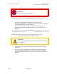
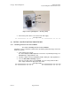
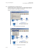
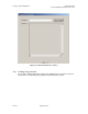
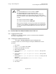
Table Of Contents
- UNDERSTANDING THE CANOPY T1/E1 MULTIPLEXER
- Status LEDS
- Physical Specifications
- Technical Specifications
- T1 Channel Mode
- E1 Channel Mode
- Alternate Mark Inversion (AMI)
- The 1 in 15 Requirement (AMI)
- Binary Eight Zero Substitution Coding
- High Density Bipolar Order Three Encoding
- Master and Secondary Clocks
- Loss of Clock Signal
- Timing Modes
- Loopback Timing Mode
- Recovered Timing Mode
- Network Timing Scenarios
- INSTALLING AND CONFIGURING YOUR CANOPY T1/E1 MULTIPLEXERS
- MANAGING YOUR CANOPY T1/E1 MULTIPLEXERS
- CANOPY T1/E1 MULTIPLEXER REFERENCE INFORMATION
- Canadian Compliance Statement
- Statement of Compliance
Canopy T1/E1MultiplexerSeptember2004
T1/E1MultiplexerFPGAVersion3.4
Page32 of 73
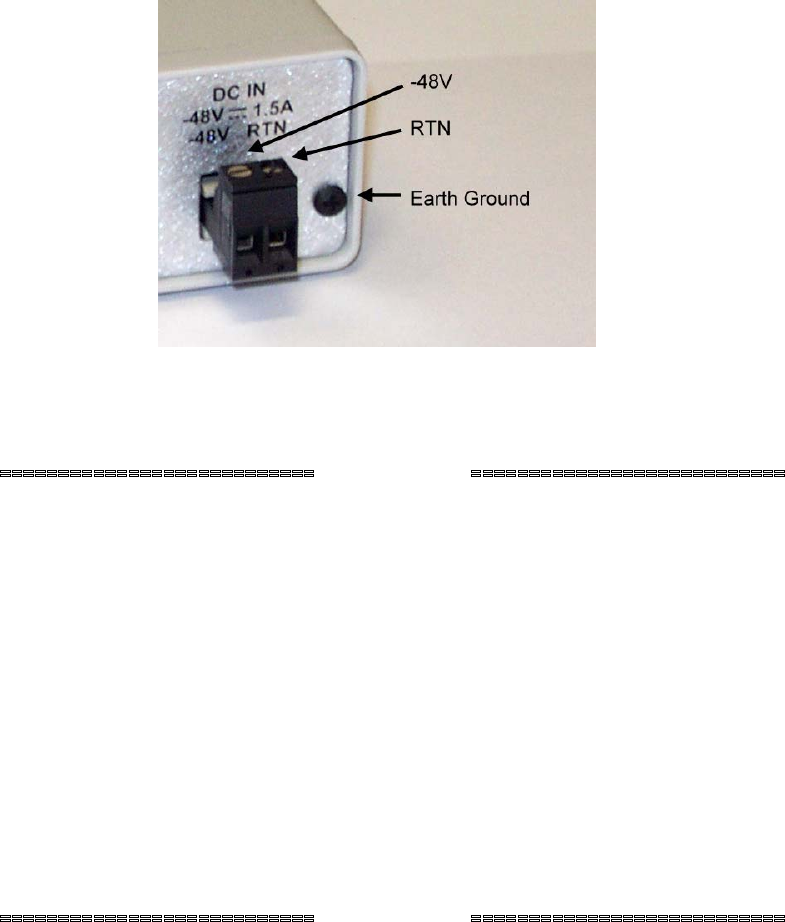
Figure 13: Rear panel Option 2: −48 v DC polarity
3. Connect the power cables to an external −48 v DC supply.
end of procedure
2.3 INITIALCONFIGURATIONPROCEDURES
2.3.1 InstallingSoftwarefromthe CD ‐ROM
Procedure 5: Installing Software from the CD-ROM
Follow these steps to install the software that is provided by Motorola Canopy on the CD-
ROM onto your PC.
1. Load software onto your PC.
The T1/E1 Multiplexer EMS Graphical User Interface is provided by Canopy on a
CD-ROM that is shipped with the unit.
2. Install the software from the CD-ROM by double-clicking the setup application or
3. Issue the Start->Run->d:/setup sequence
where d: is the drive letter of your CD-ROM. If you are using a different drive
letter, simply substitute the appropriate drive letter.
end of procedure
Issue3