
Switch User Guide
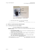
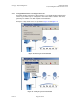
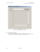
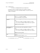
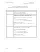
Table Of Contents
- UNDERSTANDING THE CANOPY T1/E1 MULTIPLEXER
- Status LEDS
- Physical Specifications
- Technical Specifications
- T1 Channel Mode
- E1 Channel Mode
- Alternate Mark Inversion (AMI)
- The 1 in 15 Requirement (AMI)
- Binary Eight Zero Substitution Coding
- High Density Bipolar Order Three Encoding
- Master and Secondary Clocks
- Loss of Clock Signal
- Timing Modes
- Loopback Timing Mode
- Recovered Timing Mode
- Network Timing Scenarios
- INSTALLING AND CONFIGURING YOUR CANOPY T1/E1 MULTIPLEXERS
- MANAGING YOUR CANOPY T1/E1 MULTIPLEXERS
- CANOPY T1/E1 MULTIPLEXER REFERENCE INFORMATION
- Canadian Compliance Statement
- Statement of Compliance
Canopy T1/E1MultiplexerSeptember2004
T1/E1MultiplexerFPGAVersion3.4
Page33 of 73
2.3.2 UsingEMSSoftwaretoConfiguretheUnit
An intuitive graphic unit interface (GUI) provides a user-friendly graphical display that
allows easy-to-follow steps to configure the unit. Fault isolation, statistics and events
gathering are available. The GUI simplifies field installation.
Examples of drop-down menus are provided in Figure 14 and Figure 15.
Figure 14: File drop-down menu in GUI
Figure 15: Config drop-down menu in GUI
Issue3