
Switch User Guide
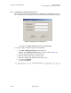
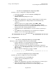
Table Of Contents
- UNDERSTANDING THE CANOPY T1/E1 MULTIPLEXER
- Status LEDS
- Physical Specifications
- Technical Specifications
- T1 Channel Mode
- E1 Channel Mode
- Alternate Mark Inversion (AMI)
- The 1 in 15 Requirement (AMI)
- Binary Eight Zero Substitution Coding
- High Density Bipolar Order Three Encoding
- Master and Secondary Clocks
- Loss of Clock Signal
- Timing Modes
- Loopback Timing Mode
- Recovered Timing Mode
- Network Timing Scenarios
- INSTALLING AND CONFIGURING YOUR CANOPY T1/E1 MULTIPLEXERS
- MANAGING YOUR CANOPY T1/E1 MULTIPLEXERS
- CANOPY T1/E1 MULTIPLEXER REFERENCE INFORMATION
- Canadian Compliance Statement
- Statement of Compliance

Canopy T1/E1MultiplexerSeptember2004
T1/E1MultiplexerFPGAVersion3.4
Page41 of 73
Action Steps
Set timing mode
NOTE: Timing mode applies to all four T1 lines. Loopback mode loops the
T1/E1 Tx clock to the T1/E1 Rx. Recovered mode recovers the T1/E1 clock
from the incoming T1/E1 over Ethernet bit stream (recovers the clock from
the far end T1/E1). The default timing mode is Recovered.
Enter set clock source [loopback/recovered]
where
[loopback/recovered] represents the clock timing mode.
RESULT: The system responds
Clock source is [loopback/recovered]
Set master clock
reference line
NOTE:This is the master clock reference for all four T1/E1 lines.
The default setting is T1/E1 Port 1.
Enter set master clock reference line [1/2/3/4]
where
[1/2/3/4] represents T1/E1 ports 1 through 4.
RESULT: The system responds
Clk ref line; [1,2,3,4]
Set backup clock
reference line
NOTE: This is the optional backup clock reference for all four T1/E1 lines.
The backup clock reference becomes active only when the master clock
reference line is unavailable. The default setting is T1/E1 Port 2.
Enter set secondary clock reference line [1/2/3/4]
where
[1/2/3/4] represents T1/E1 ports 1 through 4.
RESULT: The system responds
Backup clk ref line; [1/2/3/4]
Log off
Enter lo.
RESULT: The system responds goodbye.
end of procedure
Issue3