
Switch User Guide
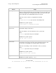
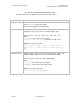
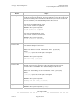
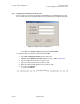
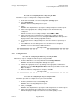
Table Of Contents
- UNDERSTANDING THE CANOPY T1/E1 MULTIPLEXER
- Status LEDS
- Physical Specifications
- Technical Specifications
- T1 Channel Mode
- E1 Channel Mode
- Alternate Mark Inversion (AMI)
- The 1 in 15 Requirement (AMI)
- Binary Eight Zero Substitution Coding
- High Density Bipolar Order Three Encoding
- Master and Secondary Clocks
- Loss of Clock Signal
- Timing Modes
- Loopback Timing Mode
- Recovered Timing Mode
- Network Timing Scenarios
- INSTALLING AND CONFIGURING YOUR CANOPY T1/E1 MULTIPLEXERS
- MANAGING YOUR CANOPY T1/E1 MULTIPLEXERS
- CANOPY T1/E1 MULTIPLEXER REFERENCE INFORMATION
- Canadian Compliance Statement
- Statement of Compliance

Canopy T1/E1MultiplexerSeptember2004
T1/E1MultiplexerFPGAVersion3.4
Page44 of 73
2.4.6 ConfigureTiming
Before the timing may be configured, you need to determine the network timing scheme
to be used. You also need to identify the master and slave devices for the end-user PBX
equipment.
Procedure 13: Configuring timing using the CLI
Action Steps
Log in Press Enter.
At the username prompt, enter admin.
At the password prompt, enter password.
Set master clock
reference line
NOTE:This is the master clock reference for all four T1/E1 lines.
The default setting is T1/E1 Port 1.
Enter set master clock reference line [1/2/3/4]
where
[1/2/3/4] represents T1/E1 ports 1 through 4.
RESULT: The system responds
Clk ref line; [1,2,3,4]
Set backup clock
reference line
NOTE: This is the optional backup clock reference for all four T1/E1 lines. The
backup clock reference becomes active only when the master clock reference
line is unavailable. The default setting is T1/E1 Port 2.
Enter set secondary clock reference line [1/2/3/4]
where
[1/2/3/4] represents T1/E1 ports 1 through 4.
RESULT: The system responds
Backup clk ref line; [1/2/3/4]
Issue3