
Switch User Guide
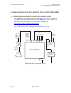
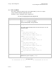
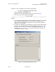
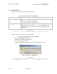
Table Of Contents
- UNDERSTANDING THE CANOPY T1/E1 MULTIPLEXER
- Status LEDS
- Physical Specifications
- Technical Specifications
- T1 Channel Mode
- E1 Channel Mode
- Alternate Mark Inversion (AMI)
- The 1 in 15 Requirement (AMI)
- Binary Eight Zero Substitution Coding
- High Density Bipolar Order Three Encoding
- Master and Secondary Clocks
- Loss of Clock Signal
- Timing Modes
- Loopback Timing Mode
- Recovered Timing Mode
- Network Timing Scenarios
- INSTALLING AND CONFIGURING YOUR CANOPY T1/E1 MULTIPLEXERS
- MANAGING YOUR CANOPY T1/E1 MULTIPLEXERS
- CANOPY T1/E1 MULTIPLEXER REFERENCE INFORMATION
- Canadian Compliance Statement
- Statement of Compliance
Canopy T1/E1MultiplexerSeptember2004
T1/E1MultiplexerFPGAVersion3.4
Page55 of 73
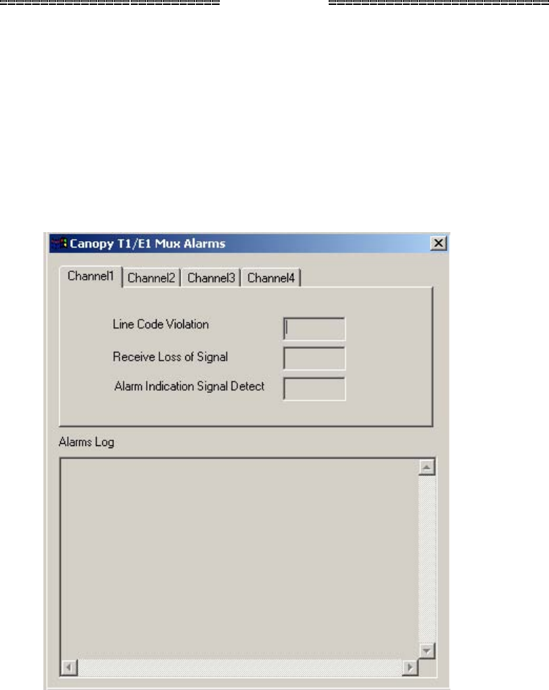
Follow these steps to display the T1/E1 alarms using the EMS.
Procedure 24: Displaying alarms using the EMS
1. Select the Alarms→T1/E1 Alarms menu.
RESULT: The T1/E1 Alarms window pops up as shown in Figure 21.
2. Select the desired T1/E1 Channel (1 through 4).
end of procedure
NOTES:
1. The T1/E1 alarms will be displayed, with a green light meaning no current alarms
and a red light meaning that there is a current alarm. The alarms are also
displayed in text form: No means that there is not a current alarm. Yes means
that there is a current alarm.
2. The Alarms Log window lists alarms that have occurred for all 4 T1/E1s while the
window is open. An alarm log file is automatically written for all 4 T1/E1s. The
file exits in the same directory in which the T1/E1 Multiplexer EMS exists. The
filename is apt1AlarmsLog.txt. The log file can be written only when the
T1/E1 Multiplexer EMS is running.
Figure 21: Canopy T1/E1 Mux Alarms window
Issue3