
Switch User Guide
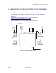
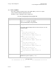
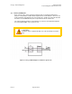
Table Of Contents
- UNDERSTANDING THE CANOPY T1/E1 MULTIPLEXER
- Status LEDS
- Physical Specifications
- Technical Specifications
- T1 Channel Mode
- E1 Channel Mode
- Alternate Mark Inversion (AMI)
- The 1 in 15 Requirement (AMI)
- Binary Eight Zero Substitution Coding
- High Density Bipolar Order Three Encoding
- Master and Secondary Clocks
- Loss of Clock Signal
- Timing Modes
- Loopback Timing Mode
- Recovered Timing Mode
- Network Timing Scenarios
- INSTALLING AND CONFIGURING YOUR CANOPY T1/E1 MULTIPLEXERS
- MANAGING YOUR CANOPY T1/E1 MULTIPLEXERS
- CANOPY T1/E1 MULTIPLEXER REFERENCE INFORMATION
- Canadian Compliance Statement
- Statement of Compliance
Canopy T1/E1MultiplexerSeptember2004
T1/E1MultiplexerFPGAVersion3.4
Page57 of 73
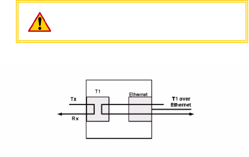
3.4 T1/E1LOOPBACK
Each of the 4 T1/E1s can be placed in loopback mode for testing and maintenance
purposes. This provides a bi-directional loopback on the T1/E1 interface. The near end
T1/E1 Transmit is looped back to the near end Receive, and the far end T1/E1 transmit
that arrives over the BH Ethernet port is looped back to the far end Receive.
The T1/E1 loopback remains in effect until the user removes the loopback through the
CLI or through the EMS, or the system is reset.
CAUTION!
Invoking a T1/E1 Loopback will drop voice calls and disrupt user traffic
flow.
Figure 23: Canopy T1/E1 Multiplexer in T1/E1 Loopback mode
Issue3