
Switch User Guide
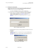
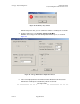
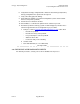
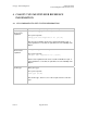
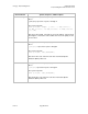
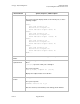
Table Of Contents
- UNDERSTANDING THE CANOPY T1/E1 MULTIPLEXER
- Status LEDS
- Physical Specifications
- Technical Specifications
- T1 Channel Mode
- E1 Channel Mode
- Alternate Mark Inversion (AMI)
- The 1 in 15 Requirement (AMI)
- Binary Eight Zero Substitution Coding
- High Density Bipolar Order Three Encoding
- Master and Secondary Clocks
- Loss of Clock Signal
- Timing Modes
- Loopback Timing Mode
- Recovered Timing Mode
- Network Timing Scenarios
- INSTALLING AND CONFIGURING YOUR CANOPY T1/E1 MULTIPLEXERS
- MANAGING YOUR CANOPY T1/E1 MULTIPLEXERS
- CANOPY T1/E1 MULTIPLEXER REFERENCE INFORMATION
- Canadian Compliance Statement
- Statement of Compliance
Canopy T1/E1MultiplexerSeptember2004
T1/E1MultiplexerFPGAVersion3.4
Page62 of 73
Figure 28: Invalid key entry window
NOTE: At any later date, you can confirm the number of enabled ports as follows.
4. From the main menu, select Config→Canopy T1/E1 Mux.
RESULT: The Canopy T1/E1 Mux Configuration window opens, as shown in
Figure 29.
Figure 29: Canopy T1/E1 Mux Configuration window
5. In the lower right quadrant of the window, find the Enabled T1/E1 Ports block.
NOTE: Each enabled port is identified by a black check mark.
end of procedure
Issue3