
Switch User Guide
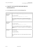
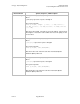
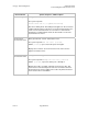
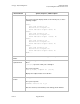
Table Of Contents
- UNDERSTANDING THE CANOPY T1/E1 MULTIPLEXER
- Status LEDS
- Physical Specifications
- Technical Specifications
- T1 Channel Mode
- E1 Channel Mode
- Alternate Mark Inversion (AMI)
- The 1 in 15 Requirement (AMI)
- Binary Eight Zero Substitution Coding
- High Density Bipolar Order Three Encoding
- Master and Secondary Clocks
- Loss of Clock Signal
- Timing Modes
- Loopback Timing Mode
- Recovered Timing Mode
- Network Timing Scenarios
- INSTALLING AND CONFIGURING YOUR CANOPY T1/E1 MULTIPLEXERS
- MANAGING YOUR CANOPY T1/E1 MULTIPLEXERS
- CANOPY T1/E1 MULTIPLEXER REFERENCE INFORMATION
- Canadian Compliance Statement
- Statement of Compliance

Canopy T1/E1MultiplexerSeptember2004
T1/E1MultiplexerFPGAVersion3.4
Page69 of 73
Desired Action Syntax, Response, and Description
Get the timing mode Enter get clock source
The system responds
Clock source set to [loopback/recovered]
Gets the T1 timing mode. This timing mode applies for all four T1 lines.
Loopback mode means to take the T1 Tx clock and loop it back to the
T1 Rx. Recovered mode means to recover the T1 clock from the
incoming T1 over Ethernet bit stream, in other words to recover the
clock from the far end T1.
Get the master
clock reference line
Enter get master clock reference line
The system responds Clk ref line: [1/2/3/4]
NOTE: [1/2/3/4] represents T1/E1 ports 1 through 4.
Displays the T1 master clock reference line. This clock reference
applies for all four T1 lines.
Get the secondary
clock reference line
Enter get secondary clock reference line
The system responds Backup clk ref line; [1/2/3/4]
NOTE:
[1/2/3/4] represents T1/E1 ports 1 through 4.
Displays the T1/E1 secondary or backup clock reference line. This
clock reference is the backup clock reference for all four T1/E1 lines.
The backup clock reference will become active only when the master
clock reference line is unavailable.
Issue3