Installing Motorola Private Broadband Networks Motorola Private Broadband Networks (PBN) extend layer-2 Ethernet over telephone grade wiring at varying distances from 600 meters to 3000 meters. Each product has value-added features, designed for specific applications and markets. Network managers will be familiar with common networking tasks such as 802.1Q VLANs, QoS, Access Control Lists, SNMP, etc. Understanding the physical installation routines is critical to a successful installation.
TABLE OF CONTENTS Introduction .........................................................................................................3 Simple Network Topology ....................................................................................................... 3 T3 PowerBroadband System .................................................................................................. 5 XLP-6800 System .....................................................................................................
Introduction All products share a common operating system, CLI syntax, web UI, and SNMP MIBs. In all cases, 802.1Q VLANs and QoS can be managed through the entire network from the core switch to each remote Ethernet port. An important feature in common with all products is line power. The remote client device (also called a CPE) is line powered from the core switch installed in a central wiring closet. Pay close attention to the difference in line power function for each product.
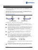
as wireless access points and IP cameras to the CPE (B). T3 does not provide PoE on the downstream Ethernet ports.
T3 PowerBroadband System The T3 system is designed primarily for hospitality, but useful in any high density MDU type installation. The centrally installed T3 PowerBroadband Switch has 25 ports for downstream CPEs, and 2 x GigE uplink ports. Two different types of remote CPEs are supported. m2 WallPlate The m2 WallPlate is a managed, Ethernet-only device. It has two 10/100Mb Ethernet ports to connect with access devices. 802.
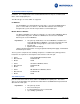
The XLP-6800 system is comprised of the following components: • • • Name: Motorola P/N: Model: XLP-6824 Master for PowerBroadband PoE, RoHS 552681-001-00 43114 • • • Name: Motorola P/N: Model: XLP-6802 Client, RoHS 552679-001-00 43002 XLP-7000 System (not released as of 01/01/09. Available for beta evaluation) XLP-7038 has eight ports for connection to remote clients, and one GigE uplink port. The remote device is the XLP-701, with one 802.3af PoE Ethernet port.
XLP-7000 Extended PoE System Motorola, Inc Page 7 of 24
T3 PowerBroadband System - Installation 1) Install the switch in the central telephone room a) Install switch and other network devices in equipment rack b) Interconnect the switch with the premises telephone wiring 2) Install the CPE devices a) Install filters on all other phones b) Enable line power, test Type of Connectors Used The T3 system employs three types of connectors.
Cross connect wire spool, 300m 19" Equipment Rack Misc (AC power strip, wire management, etc) UPS or line conditioning power Aggregation Layer2 Ethernet Switch One spool for ~100 rooms, as needed As needed As needed As needed As needed Note on Filters Only Motorola filters can be used when line power is enabled. Typical ADSL type filters do not have enough filtering capability.
25-pr Amphenol LINE 25-pr Amphenol PHONE Motorola T3 Switch Motorola, Inc Page 10 of 24
Install the Cross Connects If doing a hotel installation, identify the line 1 wire pair. The recommended procedure is to begin replacing cross connects at the room termination block, moving back to the PBX termination block. The reason is simple: In most cases, the room termination blocks are marked with room numbers; whereas the PBX block is marked with cable pairs or PBX port IDs.
S t e p T w o - I n s t al l t h e W al l P l at e The Motorola WallPlate is designed to be installed over an existing RJ11 wall jack. In cases where this is not possible; install the WallPlate next to the telephone jack, and route the telephone cable through the small “mouse hole” in the side.
S t ep Th re e - E n a b l e x D S L l i n e s, en a b l e l i n e p o w e r, t e st NOTE: Do not enable line power until filters have been installed on all telephones sharing the wire pair. If line power is enabled without a filter, the phones will ring. For a detailed list of commands, refer to the T2 or T3 Command Reference guide or T3 User Guide. Details are available for configuring IP address, ACL, SNMP, VLANs, QoS, SNTP, IGMP, etc.
XLP-6800 Extended PoE System - Installation 1) Install the XLP-6824 switch in the central wiring closet a) Install switch and other network devices in equipment rack b) Interconnect the switch with the premises wiring 2) Install the CPE devices a) Enable line power, check line status b) Enable PoE power, check remote PoE device status i) Note the XLP-6802 supports 2 x 10/100Mb PoE devices Type of Connectors Used The XLP-6824 uses three types of connectors: 1) DB9 straight wired serial connector used for con
S t e p O n e - I n s t al l t h e X L P - 6 8 2 4 S w i t c h a n d c l i e n t Install the Switch in a standard EIA-19 equipment rack using the provided mounting ears. Install other network equipment such as routers and Ethernet switches. Premises termination with the XLP-6824 is normally done by directly punching the wire pairs to a termination block. No cross connect is required since the XLP system is not compatible with telephone wiring in the same wire pair.
Review the diagnostics and monitoring section at the end of the document for explanation of the line monitoring parameters.
XLP-7038 Extended PoE System - Installation 1) Install the XLP-7038 switch in the central wiring closet a) Install switch and other network devices in equipment rack b) Interconnect the switch with the premises wiring 2) Install the CPE devices a) Enable line power, check line status b) Enable PoE power, check remote PoE device status i) Note the XLP-701 supports 1 x 10/100Mb PoE devices Type of Connectors Used The XLP-7038 uses three types of connectors: 4) DB9 straight wired serial connector used for cons
S t e p O n e - I n s t al l t h e X L P - 7 0 3 8 S w i t c h a n d c l i e n t Install the Switch in a standard EIA-19 equipment rack using the provided mounting ears. Install other network equipment such as routers and Ethernet switches. Premises termination with the XLP-7038 is normally done by directly punching the wire pairs to a termination block. No cross connect is required since the XLP system is not compatible with telephone wiring in the same wire pair.
Diagnostics Wi r e p a i r sh or t e d If wire pairs are shorted on any product, line power will be disabled. With the T3, a wire short can be difficult to detect due to the method of power generation. On XLP products, wire shorts are easily identified. T3 PowerBroadband Cmd: show interface dsl status This one command provides most of the details you will need to diagnose T3 systems. Copy the output of this command to notepad for further analysis.
XLP-6824/XLP-7038 Power is managed at two distinct hardware locations. Power applied on the premises wire between the switch and the CPE - is controlled by the power control circuitry inside the XLP master switch. Power over Ethernet on the XLP client is controlled by a PoE controller. Cmd: show interface dsl power status Use this command to view the state of line power on the switch.
L e s s t h an e x p e c t e d p e r f o r m a n c e Bandwidth on each line can vary depending on many factors including electrical noise, crosstalk and wire type. Motorola customer support can provide detailed assistance in fine-tuning parameters for maximum performance. The following steps will suffice in most cases. T3 PowerBroadband and XLP-7000 Cmd: show interface dsl status Excessive Crosstalk What to do Crosstalk is caused by low twist wire pairs.
only when the wire twist and quality is known to be good. Wire type must be Cat-3 or higher. On Cat-3 or lower wire, select a lower numbered bandplan, such as 40-40 or 30-30. Use the command, interface dsl profile to select a lower bandplan. For example, interface dsl profile 30-30. If the line will not link at all, start at the 5-5 profile, using the command interface dsl profile 5-5. After a successful link, select a higher profile.
A pp en di x A Definitions Common telephony terms used in this document. PSTN Public Switched Telephone Network. Local telephone service providing a direct circuit to the property from a central office. The T3 system cannot be connected to the PSTN. PBX Private Branch eXchange. A telephone system installed and maintained by a property owner, such as a hotel operator. A PBX allows a large number of users to share a limited number of external lines connected to the PSTN.
Photos of Typical Hotel PBX The following pictures illustrate a typical layout of the PBX, RJ21 cables, and cross connect blocks. PBX with RJ21 Cables Wire Trays to manage the RJ21 cable bundles Line Termination Blocks The PBX Amphenol cables are punched down behind the 110 blocks in this picture.