
Installation manual
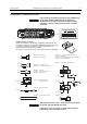
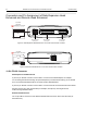
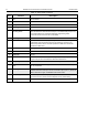
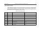

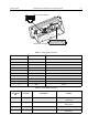
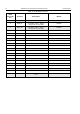
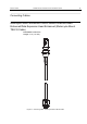
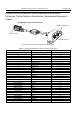
Table Of Contents
- COPYRIGHT
- IMPORTANT SAFETY INFORMATION
- DOCUMENT HISTORY
- CONTENTS
- SCOPE
- MODEL INFORMATION & ACCESSORIES
- INSTALLATION
- Introduction
- DC Power Cable Installation
- Ignition Sense Cable Installation
- Terminal Installation
- Enhanced Control Head Installation
- Trunnion Installation
- Dashboard Installation
- Desktop Installation
- Remote Mount Installation
- Installing the Remote Mount Enhanced Control Head onto the Remote Mount Trunnion
- Installing the Remote Mount Enhanced Control Head in a DIN Mount Bracket
- Inserting the Remote Mount Enhanced Control Head with the DIN Mount Bracket into the DIN Frame
- Adding Extra Connectivity to the Remote Head
- Installing the Accessories Expansion Cable
- Motorcycle Mount Enhanced Control Head Installation
- Data Expansion Head Enhanced Installation
- Connectors and Pin Assignment of the Radio
- Connectors and Pin Assignment of Data Expansion Head Enhanced and Remote Head Enhanced
- Connector and Pin Assignment of the Enhanced Control Head
- Connecting Cables
- Motorcycle Mount Enhanced Control Head-to-Remote Head Enhanced/Data Expansion Head Enhanced (Motorcycle Mount TELCO Cable)
- Remote Mount Enhanced Control Head/Motorcycle Mount Enhanced Control Head-to-Accessories (Accessories Expansion Cable)
- Radio-to-Junction Box
- Data Expansion Head Enhanced Radio-to-Data Device
- Data Expansion Head Enhanced Radio-to-Fist Microphone
- Radio-to-Data Device: Active Data Cable
- Vehicle Antenna Installation
- External Speaker Installation
- UPGRADING THE TERMINAL
- APPENDIX

INSTALLATION MTM800 Enhanced Mobile Terminal Installation Manual 61
Accessory Connection Plan
The accessory connections shown are not compatible to
some other models of Motorola radios. Check the
appropriate accessory or technical manual for further
information. Ensure correct position of the accessory
connector.
DO NOT short pin 16 or pin 1 on the accessory connector
to ground; this may damage the radio.
If the ignition line is not used, it needs to be grounded.
Interference can cause radio to hang.
16-pin Accessory Connector
15
16
1
2
The 16-pin connector, Part Number: 1580922V01 (delivered with the
accessory connector kit, Part Number: GMBN1021) plugs into the centre
of the 20-pin accessory connector. The four outside pins are not
connected, see grey square at figure above.
(Alternatively, a 20-pin connector can be used as well, Part Number: 1586184B01).
86
85
87
30
+12V
Ext. Alarm 4
86
85
87
30
+12V
Ext. Alarm 4
+12V
+12V
SWB+ 13
4A
+12V
Ignition 10
1
16
GND 7
MIC 2
PTT 3
GND 8
Emergency 9
12k
GND 8
4
13
GMSN4066 Speaker 13W
GMSN4078 Speaker 5W
GMMN4065 Visor Microphone
GMMN1033 Visor Mic, omni directional
RLN4856 Footswitch
RLN4857 Pushbutton w/Remote PTT
RLN4858 Gooseneck PTT
RLN4836 Tri-state Emergency
Footswitch and Cable
HKN9327 Ignition Sense Cable
GLN7282 Buzzer
GKN6272 External Alarm, Relay and Cable
Car
Ignition Switch
GMKN4084 Speaker Extension Cable
GMBN1021 Accessory connector kit containing:
Seal, Part No 3202606Y02
Accessory Connector Housing 16-Pin, Part No 1580922V01
Crimp Contact, Part No 2984249N01
1
16
1
16
1816141210
1715
13119753
1
19
864220
*Note the location of Pin 1
Accessory Connector