
Installation manual
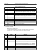
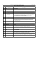
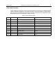

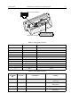
Table Of Contents
- COPYRIGHT
- IMPORTANT SAFETY INFORMATION
- DOCUMENT HISTORY
- CONTENTS
- SCOPE
- MODEL INFORMATION & ACCESSORIES
- INSTALLATION
- Introduction
- DC Power Cable Installation
- Ignition Sense Cable Installation
- Terminal Installation
- Enhanced Control Head Installation
- Trunnion Installation
- Dashboard Installation
- Desktop Installation
- Remote Mount Installation
- Installing the Remote Mount Enhanced Control Head onto the Remote Mount Trunnion
- Installing the Remote Mount Enhanced Control Head in a DIN Mount Bracket
- Inserting the Remote Mount Enhanced Control Head with the DIN Mount Bracket into the DIN Frame
- Adding Extra Connectivity to the Remote Head
- Installing the Accessories Expansion Cable
- Motorcycle Mount Enhanced Control Head Installation
- Data Expansion Head Enhanced Installation
- Connectors and Pin Assignment of the Radio
- Connectors and Pin Assignment of Data Expansion Head Enhanced and Remote Head Enhanced
- Connector and Pin Assignment of the Enhanced Control Head
- Connecting Cables
- Motorcycle Mount Enhanced Control Head-to-Remote Head Enhanced/Data Expansion Head Enhanced (Motorcycle Mount TELCO Cable)
- Remote Mount Enhanced Control Head/Motorcycle Mount Enhanced Control Head-to-Accessories (Accessories Expansion Cable)
- Radio-to-Junction Box
- Data Expansion Head Enhanced Radio-to-Data Device
- Data Expansion Head Enhanced Radio-to-Fist Microphone
- Radio-to-Data Device: Active Data Cable
- Vehicle Antenna Installation
- External Speaker Installation
- UPGRADING THE TERMINAL
- APPENDIX

INSTALLATION MTM800 Enhanced Mobile Terminal Installation Manual 63
25-Pin subD Connector
Data Expansion Head Enhanced:
The radio must be turned ON/OFF via the Ignition Sense Cable HKN9327, which has to be
connected on Pin 10 of the Accessory Connector on the rear side of the radio.
Table 11 10-Pin TELCO Connector
Pin Function Description
10 Analog Ground Analog Ground
9 FLT_A+ This voltage is at battery voltage level and is available as long as the radio is
connected to the supply voltage. The maximum current is 300mA. A fuse in the
radio prevents further circuit damage in case of shorting this pin to ground.
8 SCI_TX This if for communication between the radio and the Enhanced Control Head.
7 Radio On/Off Control This is the Enhanced Control Head service request input. A level of 5 volts
indicates that the Enhanced Control Head needs to communicate with the radio. In
addition it switches on the radio's voltage regulators. The idle state is a level below
0.6V.
6 Ground Ground
5 Speaker - Negative output of the radio’s audio PA.
4 Audio- Balanced Audio - (Bidirectional)
3 BUS+ This is used for communication between the radio and an Enhanced Control Head.
2 Speaker + Positive output of the radio's audio PA.
1 Audio + Balanced Audio + (Bidirectional)
Table 12 25-Pin subD Connector
Pin Function Description
1 GND Ground
2 RS232_SCI_TX Transmit Data (4-wire RS232 with RS232 level)
3 RS232_SCI_RX Receive Data (4-wire RS232 with RS232 level)
4 RS232_RTS Request to Send (4-wire RS232 with RS232 level)
5 RS232_CTS Clear to Send (4-wire RS232 with RS232 level)
6 FLT_A+ This voltage is at battery voltage level and is available as long as the radio is
connected to the supply voltage. A fuse in the radio prevents further circuit
damage in case of shorting this pin to ground. This pin is only used together
with the pins 14, 20, and 23 to select flashing and programming mode, or to
switch the radio on.
7 Ground Ground for RS232
8 SB9600_BUSY SB9600 Busy
9 NC Not Connected