
Installation manual
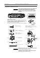
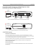
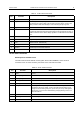
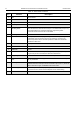
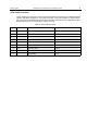

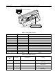
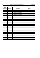
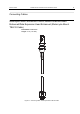
Table Of Contents
- COPYRIGHT
- IMPORTANT SAFETY INFORMATION
- DOCUMENT HISTORY
- CONTENTS
- SCOPE
- MODEL INFORMATION & ACCESSORIES
- INSTALLATION
- Introduction
- DC Power Cable Installation
- Ignition Sense Cable Installation
- Terminal Installation
- Enhanced Control Head Installation
- Trunnion Installation
- Dashboard Installation
- Desktop Installation
- Remote Mount Installation
- Installing the Remote Mount Enhanced Control Head onto the Remote Mount Trunnion
- Installing the Remote Mount Enhanced Control Head in a DIN Mount Bracket
- Inserting the Remote Mount Enhanced Control Head with the DIN Mount Bracket into the DIN Frame
- Adding Extra Connectivity to the Remote Head
- Installing the Accessories Expansion Cable
- Motorcycle Mount Enhanced Control Head Installation
- Data Expansion Head Enhanced Installation
- Connectors and Pin Assignment of the Radio
- Connectors and Pin Assignment of Data Expansion Head Enhanced and Remote Head Enhanced
- Connector and Pin Assignment of the Enhanced Control Head
- Connecting Cables
- Motorcycle Mount Enhanced Control Head-to-Remote Head Enhanced/Data Expansion Head Enhanced (Motorcycle Mount TELCO Cable)
- Remote Mount Enhanced Control Head/Motorcycle Mount Enhanced Control Head-to-Accessories (Accessories Expansion Cable)
- Radio-to-Junction Box
- Data Expansion Head Enhanced Radio-to-Data Device
- Data Expansion Head Enhanced Radio-to-Fist Microphone
- Radio-to-Data Device: Active Data Cable
- Vehicle Antenna Installation
- External Speaker Installation
- UPGRADING THE TERMINAL
- APPENDIX

64 MTM800 Enhanced Mobile Terminal Installation Manual INSTALLATION
10 NC Not Connected
11 NC Not Connected
12 SW_B+ Switched U
B
+/100mA
13 SB9600_BUS- SB9600 BUS-
14 ON_OFF_CONTROL/
FLASH_MODE
This input is intended to switch the terminal into flashing & programming mode.
When the terminal is switched off and this pin is connected with pin 6 (FLT A+),
the terminal switches on and enters flashing & programming mode.
This is also On/Off control for Std. Control Head.
15 SB9600_BUS+ SB9600 BUS+.
16 Internal Mic Audio This input depends on radio programming mode. This microphone signal is
independent of the microphone signal on the accessory connector. The
nominal input level is 80 mV. The DC impedance is 660 ohms and the AC
impedance is 560 ohms.
17 SB9600-Reset This output can be used to reset a SB9600 device.
18 NC Not Connected
19 GROUND Ground
20 IGNITION The radio can be switched on by connecting this pin with pin 6 (FLT A+). As
long as both pins are connected, the radio will be switched on.
21 ON_OFF_GND This is On/Off control for the old Control Head “J” (MTM300 Control Head)
22 EXPANSION-
PTT
When this input is used to key up the transmitter, the internal Mic Audio input
(pin 16) is selected.
23 SB9600_SW This input is intended to switch into SB9600 mode. The terminal must be
switched off and then this input must be connected to pin 6 (FLT A+). When the
radio is switched on again, the SB9600 mode will be active.
24 HANDSET_AUDIO This is a low power audio output primarily intended for a connected handset.
the Dc level is 4.6 V and the AC level depends on the volume setting.
25 NC Not Connected
Table 12 25-Pin subD Connector
Pin Function Description