
Installation manual
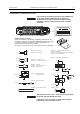
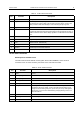
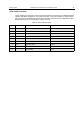

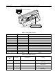
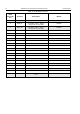
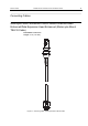
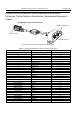
Table Of Contents
- COPYRIGHT
- IMPORTANT SAFETY INFORMATION
- DOCUMENT HISTORY
- CONTENTS
- SCOPE
- MODEL INFORMATION & ACCESSORIES
- INSTALLATION
- Introduction
- DC Power Cable Installation
- Ignition Sense Cable Installation
- Terminal Installation
- Enhanced Control Head Installation
- Trunnion Installation
- Dashboard Installation
- Desktop Installation
- Remote Mount Installation
- Installing the Remote Mount Enhanced Control Head onto the Remote Mount Trunnion
- Installing the Remote Mount Enhanced Control Head in a DIN Mount Bracket
- Inserting the Remote Mount Enhanced Control Head with the DIN Mount Bracket into the DIN Frame
- Adding Extra Connectivity to the Remote Head
- Installing the Accessories Expansion Cable
- Motorcycle Mount Enhanced Control Head Installation
- Data Expansion Head Enhanced Installation
- Connectors and Pin Assignment of the Radio
- Connectors and Pin Assignment of Data Expansion Head Enhanced and Remote Head Enhanced
- Connector and Pin Assignment of the Enhanced Control Head
- Connecting Cables
- Motorcycle Mount Enhanced Control Head-to-Remote Head Enhanced/Data Expansion Head Enhanced (Motorcycle Mount TELCO Cable)
- Remote Mount Enhanced Control Head/Motorcycle Mount Enhanced Control Head-to-Accessories (Accessories Expansion Cable)
- Radio-to-Junction Box
- Data Expansion Head Enhanced Radio-to-Data Device
- Data Expansion Head Enhanced Radio-to-Fist Microphone
- Radio-to-Data Device: Active Data Cable
- Vehicle Antenna Installation
- External Speaker Installation
- UPGRADING THE TERMINAL
- APPENDIX

INSTALLATION MTM800 Enhanced Mobile Terminal Installation Manual 65
9-Pin subD Connector
The pin assignment of this 9-pin subD connector will follow the requirements of an RS232 standard
interface with RS232 voltage level. The cable (see section
“Connecting Cables” on page 69) which
has to be used is a standardized serial interface cable which allows to connect a data device with an
RS232 Interface such as for example PC, Laptop, Console.
Table 13 9-Pin subD Connector
Pin Function Description PC Direction
1 DCD Data Carrier Detect Input
2 RXD Received Data Serial IN
3 TXD Transmitted Data Serial OUT
4 DTR Data Terminal Ready Output
5 GND Ground Output
6 DSR Data Set Ready Input
7 RTS Request to Send Output
8 CTS Clear to Send Input
9 RI Ring Indicator Input