
Installation manual
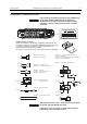
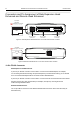
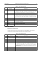
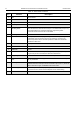
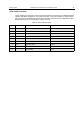

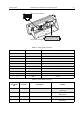
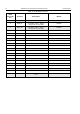
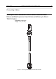
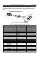
Table Of Contents
- COPYRIGHT
- IMPORTANT SAFETY INFORMATION
- DOCUMENT HISTORY
- CONTENTS
- SCOPE
- MODEL INFORMATION & ACCESSORIES
- INSTALLATION
- Introduction
- DC Power Cable Installation
- Ignition Sense Cable Installation
- Terminal Installation
- Enhanced Control Head Installation
- Trunnion Installation
- Dashboard Installation
- Desktop Installation
- Remote Mount Installation
- Installing the Remote Mount Enhanced Control Head onto the Remote Mount Trunnion
- Installing the Remote Mount Enhanced Control Head in a DIN Mount Bracket
- Inserting the Remote Mount Enhanced Control Head with the DIN Mount Bracket into the DIN Frame
- Adding Extra Connectivity to the Remote Head
- Installing the Accessories Expansion Cable
- Motorcycle Mount Enhanced Control Head Installation
- Data Expansion Head Enhanced Installation
- Connectors and Pin Assignment of the Radio
- Connectors and Pin Assignment of Data Expansion Head Enhanced and Remote Head Enhanced
- Connector and Pin Assignment of the Enhanced Control Head
- Connecting Cables
- Motorcycle Mount Enhanced Control Head-to-Remote Head Enhanced/Data Expansion Head Enhanced (Motorcycle Mount TELCO Cable)
- Remote Mount Enhanced Control Head/Motorcycle Mount Enhanced Control Head-to-Accessories (Accessories Expansion Cable)
- Radio-to-Junction Box
- Data Expansion Head Enhanced Radio-to-Data Device
- Data Expansion Head Enhanced Radio-to-Fist Microphone
- Radio-to-Data Device: Active Data Cable
- Vehicle Antenna Installation
- External Speaker Installation
- UPGRADING THE TERMINAL
- APPENDIX

66 MTM800 Enhanced Mobile Terminal Installation Manual INSTALLATION
Connector and Pin Assignment of the Enhanced Control
Head
Figure 29 View of the Enhanced Control Head’s Mobile Microphone Port Connector and Flex Cable
The keypad labelling of the control head may vary
according to the specific customer/country concerns.
Table 14 10-Pin Mobile Microphone Port (MMP) Connector
Mobile Microphone
Port Pin
Default
Functions
Alternative
Functions
USB Functions RS232 Functions
1 1-WIRE 1-WIRE 1-WIRE 1-WIRE 1-WIRE
2 GPIO_3 PTT GP Input or Output GP Input or Output RS-232-RTS
3 SPEAKER SPEAKER SPEAKER SPEAKER SPEAKER
4 GPIO_2 GPIO_2 INPUT GP Input or Output DATA - RS-232-RXD
5 GND GND GND GND GND
6 OPT 5V HIGH Impedance OPT 5V VBUS OPT 5V
7 MIC + MIC + MIC + MIC + MIC +
8 GPIO_1 GPIO_1 INPUT GP Input or Output DATA + RS-232-TXD
9 GPIO_4 HOOK GP Input or Output GP Input or Output RS-232-CTS
10 GPIO_0 GPIO_0 INPUT GP Input or Output,
PWR ON
GP Input or Output,
PWR ON
GP Input or Output,
PWR ON
o
Pin 12
Flex
Cable
21
3
7
9
10
8
4
56
Front View of the Mobile
Microphone Port (MMP)
Connector