
Installation manual
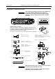
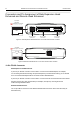
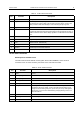
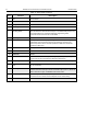
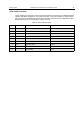

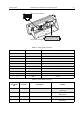
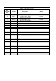
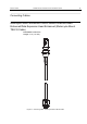
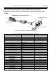
Table Of Contents
- COPYRIGHT
- IMPORTANT SAFETY INFORMATION
- DOCUMENT HISTORY
- CONTENTS
- SCOPE
- MODEL INFORMATION & ACCESSORIES
- INSTALLATION
- Introduction
- DC Power Cable Installation
- Ignition Sense Cable Installation
- Terminal Installation
- Enhanced Control Head Installation
- Trunnion Installation
- Dashboard Installation
- Desktop Installation
- Remote Mount Installation
- Installing the Remote Mount Enhanced Control Head onto the Remote Mount Trunnion
- Installing the Remote Mount Enhanced Control Head in a DIN Mount Bracket
- Inserting the Remote Mount Enhanced Control Head with the DIN Mount Bracket into the DIN Frame
- Adding Extra Connectivity to the Remote Head
- Installing the Accessories Expansion Cable
- Motorcycle Mount Enhanced Control Head Installation
- Data Expansion Head Enhanced Installation
- Connectors and Pin Assignment of the Radio
- Connectors and Pin Assignment of Data Expansion Head Enhanced and Remote Head Enhanced
- Connector and Pin Assignment of the Enhanced Control Head
- Connecting Cables
- Motorcycle Mount Enhanced Control Head-to-Remote Head Enhanced/Data Expansion Head Enhanced (Motorcycle Mount TELCO Cable)
- Remote Mount Enhanced Control Head/Motorcycle Mount Enhanced Control Head-to-Accessories (Accessories Expansion Cable)
- Radio-to-Junction Box
- Data Expansion Head Enhanced Radio-to-Data Device
- Data Expansion Head Enhanced Radio-to-Fist Microphone
- Radio-to-Data Device: Active Data Cable
- Vehicle Antenna Installation
- External Speaker Installation
- UPGRADING THE TERMINAL
- APPENDIX

70 MTM800 Enhanced Mobile Terminal Installation Manual INSTALLATION
Remote Mount Enhanced Control Head/Motorcycle Mount
Enhanced Control Head-to-Accessories (Accessories Expansion
Cable)
Part Number: PMKN4029/PMKN4056
Figure 32 Connecting Cable - Accessories Expansion Cable
Table 17 Accessories Expansion Cable, Connector Pin Function
USB A JACK Signal subD 25 Pos
1 VBUS 9
2 D- 22
3 D+ 21
4 Ground 18
Mobile Microphone Port (MMP)
1 1_WIRE 16
2 GPIO_3 (PTT) 4
3 Speaker to Headset 17
4 GPIO_2 (D-) 6
5 GPIO_1 (D+) 7
6 Ground -
7 VBUS 5
8 MIC 19
9 GPIO_4 (HOOK) 20
10 GPIO_0 8
Customised Wire Color
BROWN / BLACK GPIO_9 1
ORANGE / BLACK GPIO_6 2
YELLOW / BLACK GPIO_8 3
GREEN / BLACK TX 10
BLUE / BLACK RX 11
GRAY / BLACK MIC_2 12
BLUE Ground 13
PINK / BLACK GPIO_5 14
BLACK / WHITE GPI_7 15
BROWN / WHITE RTS 23
RED / WHITE CTS 24
ORANGE / WHITE Power On 25
RED / BLACK Headset 17
YELLOW / WHITE Ground -
subD Connector
USB Connector
Mobile Microphone Port