
- Texas Instruments Floating Point Digital Signal Processor Specification Sheet


SPRS292A − OCTOBER 2005 − REVISED NOVEMBER 2005
21
POST OFFICE BOX 1443 • HOUSTON, TEXAS 77251−1443
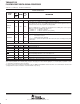
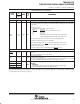
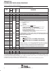
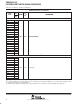
Table 15. Device Configurations Pins at Device Reset (HD[4:3], HD8, HD12, and CLKMODE0)
†
CONFIGURATION
PIN
GDP/ZDP FUNCTIONAL DESCRIPTION
HD12
‡
C15
EMIF Big Endian mode correctness (EMIFBE)
0 – The EMIF data will always be presented on the ED[7:0] side of the bus, regardless of
the endianess mode (Little/Big Endian).
1 − In Little Endian mode (HD8 =1), the 8-bit or 16-bit EMIF data will be present on the
ED[7:0] side of the bus.
In Big Endian mode (HD8 =0), the 8-bit or 16-bit EMIF data will be present on the
ED[31:24] side of the bus [default].
EMIF Big Endian mode correctness is not supported on the C6711/11B/11C device.
This new functionality does not affect systems using the current default value of HD12=1. For
more detailed information on the big endian mode correctness, see the EMIF Big Endian Mode
Correctness portion of this data sheet.
HD8
‡
B17
Device Endian mode (LEND)
0 – System operates in Big Endian mode
1 − System operates in Little Endian mode (default)
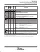
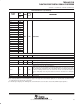
HD[4:3]
(BOOTMODE)
‡
C19, C20
Bootmode Configuration Pins (BOOTMODE)
00 – HPI boot/Emulation boot
01 – CE1 width 8-bit, Asynchronous external ROM boot with default
timings (default mode)
10 − CE1
width 16-bit, Asynchronous external ROM boot with default
timings
11 − CE1
width 32-bit, Asynchronous external ROM boot with default
timings
For more detailed information on these bootmode configurations, see the bootmode section of
this data sheet.
CLKMODE0 C4
Clock generator input clock source select
0 – Reserved. Do not use.
1 − CLKIN square wave [default]
For proper device operation, this pin must be either left unconnected or externally pulled up
with a 1-kΩ resistor.
†
All other HD pins or HD [15:13, 11:9, 7:5, 2:0] have pullups/pulldowns (IPUs or IPDs). For proper device operation of the HD [14, 13, 11:9, 7,
1, 0], do not oppose these pins with external pullups/pulldowns at reset; however, the HD[15, 6, 5, 2] pins can be opposed and driven during
reset.
‡
To ensure a proper logic level during reset when these pins are both routed out and 3−stated or not driven, it is recommended an external 10-kΩ
pullup/pulldown resistor be included to sustain the IPU/IPD, respectively.