
- Texas Instruments Floating Point Digital Signal Processor Specification Sheet


SPRS292A − OCTOBER 2005 − REVISED NOVEMBER 2005
25
POST OFFICE BOX 1443 • HOUSTON, TEXAS 77251−1443
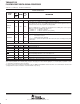
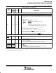
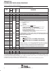
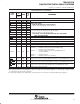
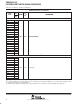
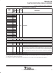
Terminal Functions (Continued)
SIGNAL
PIN
NO.
TYPE
†
IPD/
‡
DESCRIPTION
SIGNAL
NAME
GDP/
ZDP
TYPE
†
IPD/
IPU
‡
DESCRIPTION
JTAG EMULATION (CONTINUED)
EMU2 D3 I/O/Z IPU Emulation pin 2. Reserved for future use, leave unconnected.
EMU1
EMU0
B9
D9
I/O/Z IPU
For Emulation and normal operation, no external pullup/pulldown resistors are necessary. How-
ever for the Boundary Scan operation, pull down the EMU1 and EMU0 pins with a dedicated
1-kΩ resistor.
Emulation [1:0] pins.
• Select the device functional mode of operation
EMU[1:0]
Operation
00 Boundary Scan/Functional Mode (see Note)
01 Reserved
10 Reserved
11 Emulation/Functional Mode [default] (see the IEEE 1149.1
JTAG Compatibility Statement section of this data sheet)
The DSP can be placed in Functional mode when the EMU[1:0] pins are
configured for either Boundary Scan or Emulation.
Note: When the EMU[1:0] pins are configured for Boundary Scan mode, the
internal pulldown (IPD) on the TRST
signal must not be opposed in order to
operate in Functional mode.
For the Boundary Scan mode drive EMU[1:0] and RESET
pins low.
RESETS AND INTERRUPTS
RESET A13 I −−
Device reset. When using Boundary Scan mode on the device, drive the EMU[1:0] and RESET
pins low.
This pin does not have an IPU on this device.
NMI C13 I IPD
Nonmaskable interrupt
• Edge-driven (rising edge)
Any noise on the NMI pin may trigger an NMI interrupt; therefore, if the NMI pin is not used, it is
recommended that the NMI pin be grounded versus relying on the IPD.
EXT_INT7 E3
General-purpose input/output pins (I/O/Z) which also function as external
interrupts
EXT_INT6 D2
I
IPU
General-purpose input/output pins (I/O/Z) which also function as external
interrupts
Edge-driven
EXT_INT5 C1
I IPU
•
Edge-driven
•
Polarity independently selected via the External Interrupt Polarity Register
EXT_INT4 C2
•
Polarity independently selected via the External Interrupt Polarity Register
bits (EXTPOL.[3:0]), in addition to the GPIO registers.
†
I = Input, O = Output, Z = High impedance, S = Supply voltage, GND = Ground, A = Analog signal (PLL Filter)
‡
IPD = Internal pulldown, IPU = Internal pullup. [To oppose the supply rail on these IPD/IPU signal pins, use external pullup or pulldown resistors
no greater than 4.4 kΩ and 2.0 kΩ, respectively.]